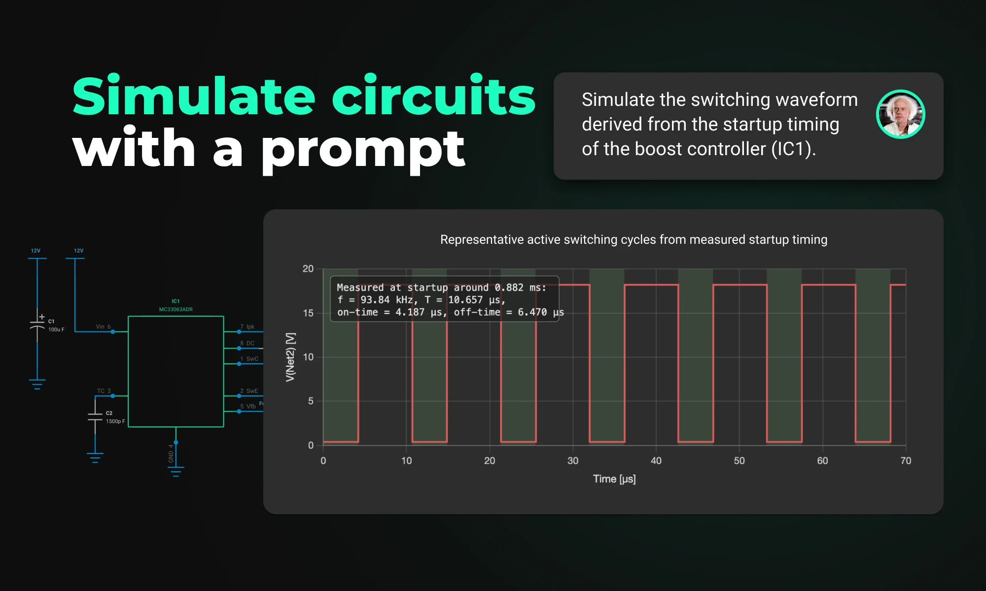
Flux brings circuit simulation to wherever you are in the design process. Start from a prompt when you have no schematic, or let Flux analyze your existing design automatically.
This update brings more than just polish—it’s the foundation for a faster, more fluid design experience, built around the way Copilot is used today and the way we see it evolving tomorrow.
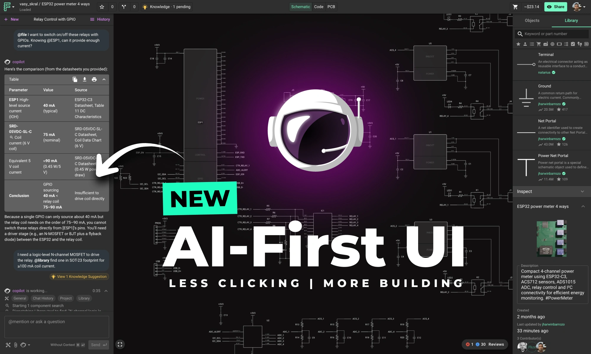
Copilot is evolving fast—from a helpful assistant to a true design partner. Today, it can generate smart BOMs, place components in your schematic, suggest replacements, and even learn how you design through custom knowledge base entries. For many workflows, it’s already the fastest way to move your project forward.
But for Copilot to truly shine, the interface needs to get out of the way.
Until now, working with Copilot often meant bouncing between tabs—opening the object browser, toggling the Inspector, trying to remember where you saw something last. That’s friction. And friction slows down flow.
So we redesigned the layout to match how modern engineers work: with AI alongside them.
This update brings more than just polish—it’s the foundation for a faster, more fluid design experience, built around the way Copilot is used today and the way we see it evolving tomorrow.
This setup reduces interface friction—less tab switching, less mouse travel, and more continuous momentum throughout your workflow. The new layout improves the core ECAD experience too—placing the object browser and Inspector side-by-side, making it easier to inspect and modify your design at a glance. Less jumping around. More flow.
This isn’t just a visual update—it’s a real improvement in how you work. With the new layout, these tasks now feel dramatically smoother:
This update is more than just a layout shift. It reflects a core belief: AI isn’t just a feature—it’s becoming the interface. Looking ahead, we’re building toward a future where hardware design starts with a conversation. You’ll always have full control—nothing is hidden in a black box—but we envision a workflow where your ideas move from prompt to PCB through an intelligent, adaptable partner. Eventually, you may find yourself managing a team of AI collaborators, each handling part of the design process in parallel, all coordinated through natural language.
Flux is getting smarter, faster, and more intuitive—so you can spend less time managing tabs and more time designing boards. Whether you’re a first-timer or returning after a break, now’s the perfect moment to jump in.
👉 Open Flux and try the new Copilot-first layout today.
This month, we’re rolling out major upgrades to Flux Copilot’s reasoning, transparency, and layout performance—plus some crucial fixes and a big leap in modular design reliability.
A few weeks ago, we launched Copilot Knowledge—a way for you to teach Copilot how you work. As you approve suggestions, they become part of your personal or project memory: vendor preferences, naming conventions, design rules, review checklists, and more.
The result? Faster decisions, fewer mistakes, and better suggestions without repeating yourself.
Now we’re introducing the next layer: System Knowledge. This is a shared, curated knowledge base built by our team of senior engineers—including folks from NASA and other top hardware teams. They’re constantly encoding real-world insights, best practices, and edge cases that help Copilot make smarter choices across the board.
By combining your personal knowledge with system-wide expertise, Copilot becomes more responsive, more accurate, and more relevant to how modern hardware actually gets built. It now blends tribal wisdom with engineering logic to solve problems that used to require manual intervention—or years of experience.
Want to shape what Copilot knows? Hit us up in Slack or Canny with ideas—naming conventions, routing strategies, design rules. The more we share, the better it gets for everyone.
No more black box. Copilot now gives real-time feedback as it processes part selections and schematic requests.
You’ll see a live execution trace—how it searches, filters, ranks, and substitutes. It’s like watching a checklist unfold in real time. Whether you’re validating a part or building a schematic from scratch, Copilot shows exactly what it’s doing, and why.
Alongside transparency, we’ve made core performance improvements to Copilot’s part-selection engine:
These changes reduce wait time, improve reliability, and keep your momentum flowing during schematic design.
Thanks to your feedback, AI Auto-Layout just got a serious upgrade:
These changes make Auto-Layout results cleaner, more production-ready, and easier to tweak.
We’re not done yet. Here’s what’s coming next:
We resolved a core issue where polygons broke inside modules—restoring full support for airwire and copper DRC checks in modular designs. Now your modules behave predictably from design to fab.
All of this is live now—log in to Flux and give the latest updates a spin. As always, keep the feedback coming. We’re building Flux Copilot with you.
This post explains key signal integrity issues like crosstalk and reflections in PCBs and offers simple layout tips to avoid them. A free guide is included.
You followed the datasheet, double-checked the footprints, and kept your traces clean. But the moment your board hits production, there’s noise on the lines, your timing margins collapse, or worse: the board doesn’t pass compliance.
This is what Signal and Power Integrity (SI/PI) is all about, and why it’s critical even for everyday designs.
Signal integrity issues fall into three buckets:
If you’re using fast clocks, long runs, or high-speed I/O—even on a two-layer board—these issues can bite.
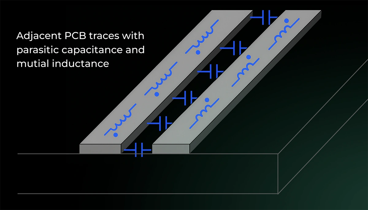
Crosstalk happens when traces run too close in parallel. The energy from one net bleeds into the other, distorting waveforms and injecting unpredictable noise.
You’ll see false triggers or glitches in digital nets, unexpected ripple in analog sections and most of the times -- EMI issues in test.
Want a shortcut? If your trace spacing is less than 3× the width, and they run in parallel for more than a few centimeters, you probably have crosstalk.
You don’t need a PhD or 8-layer board to fix this. Try these:
Board materials, stack-up, impedance, and even your decoupling caps play a role.
If your stack-up lacks solid return planes, or your dielectric isn’t up to spec, no amount of “good routing” will save you.
This is why we put together a complete guide that breaks down:
With checklists, diagrams, and cheat sheets to design boards that work the first time, for FREE.
{{download-high-speed-guide}}
Flux Copilot’s new AI-powered part search makes finding and placing components faster and easier using natural language. It eliminates tool-switching and datasheet overload. This streamlines your PCB design workflow.
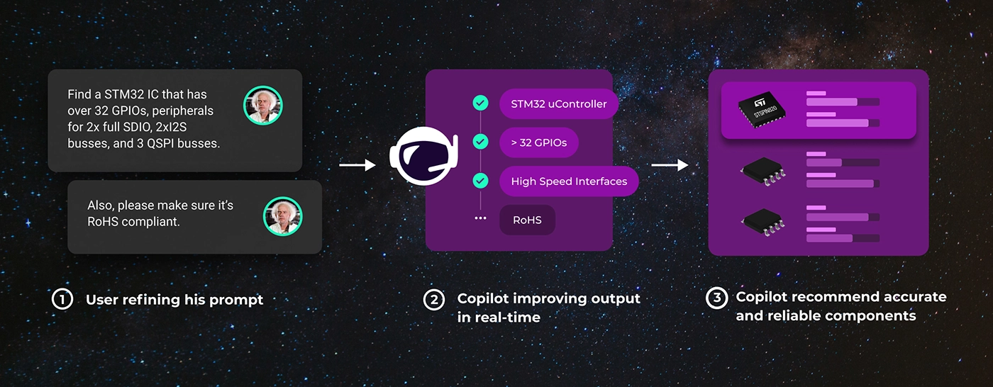
As fellow hardware designers, we know how disruptive this process can be. That’s why we’ve redesigned part search in Flux Copilot using advanced AI techniques, so you can stay focused on your design, not the scavenger hunt. Whether you're early in your journey or deep into system architecture, this upgrade makes intelligent part discovery accessible and reliable.
If you're new to PCB design, just figuring out what components to use can feel overwhelming. You might not know the terminology, part families, or what trade-offs actually matter. The goal of Copilot is to give you answers, not more decisions.
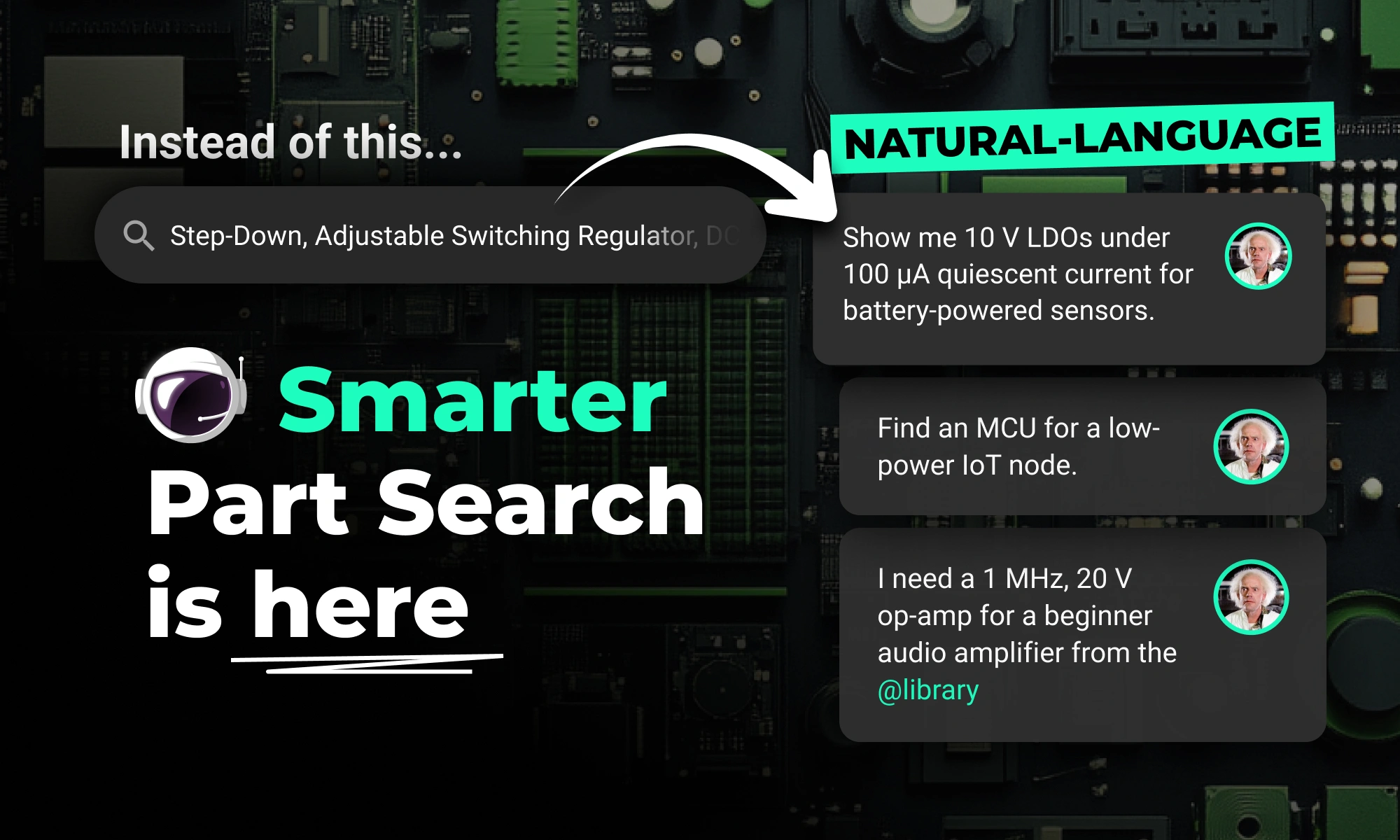
You don’t need to know the right keywords or select from dozens of confusing filters. Just describe the part you need, like you would to a teammate.
Prompt: "Find an off board molex connector with 2x6 pin configuration at 2.4mm pitch with current ratings of 500mA per pin in the @library."
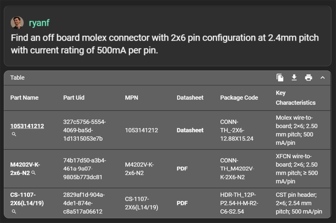
Copilot interprets the request, runs an intelligent search, and returns a clean table with real components, complete with specs, pricing, availability, and embedded datasheets.
Block diagrams are often your first step in scoping a design. But turning those blocks into real parts usually requires a second, manual pass.
Copilot eliminates that step. If you’ve created a block diagram in Flux, you can just ask:
Prompt: "Generate a BOM from this block diagram. Use parts available in the @library"
Copilot reads the intent behind each block and recommends components that fit, and are available in the library.
When you're new, it's hard to even know what to ask for. That's why Copilot uses the context of your design, voltage rails, interfaces, or constraints you've already defined, to guide its recommendations.
This is also where Copilot’s Knowledge Base really shines. If you’ve saved your preferred components, naming conventions, or layout guidelines, Copilot can use that information automatically, so its suggestions are already aligned with how you like to design.
Prompt: "Find a STM32 IC that has over 32 GPIOs, peripherals for 2x full SDIO, 2xI2S busses, and 3 QSPI busses from the @library"
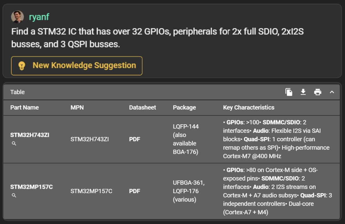
Instead of a long list of generic op-amps, you’ll get options that fit the electrical and mechanical requirements of your board, with spec highlights that make it easier to choose.
If you're an experienced designer, you already know what you're looking for. But the search process still gets in your way, especially when you’re comparing subtle trade-offs, juggling PDFs, or jumping between tools.
Copilot now lets you move from part search to placement in one continuous thread.
Looking for second sources or similar components? Copilot understands part families and common alternatives.
Prompt: "I want to add an STM32I0 from the @library to this project. Can you recommend one from that family I can use?"
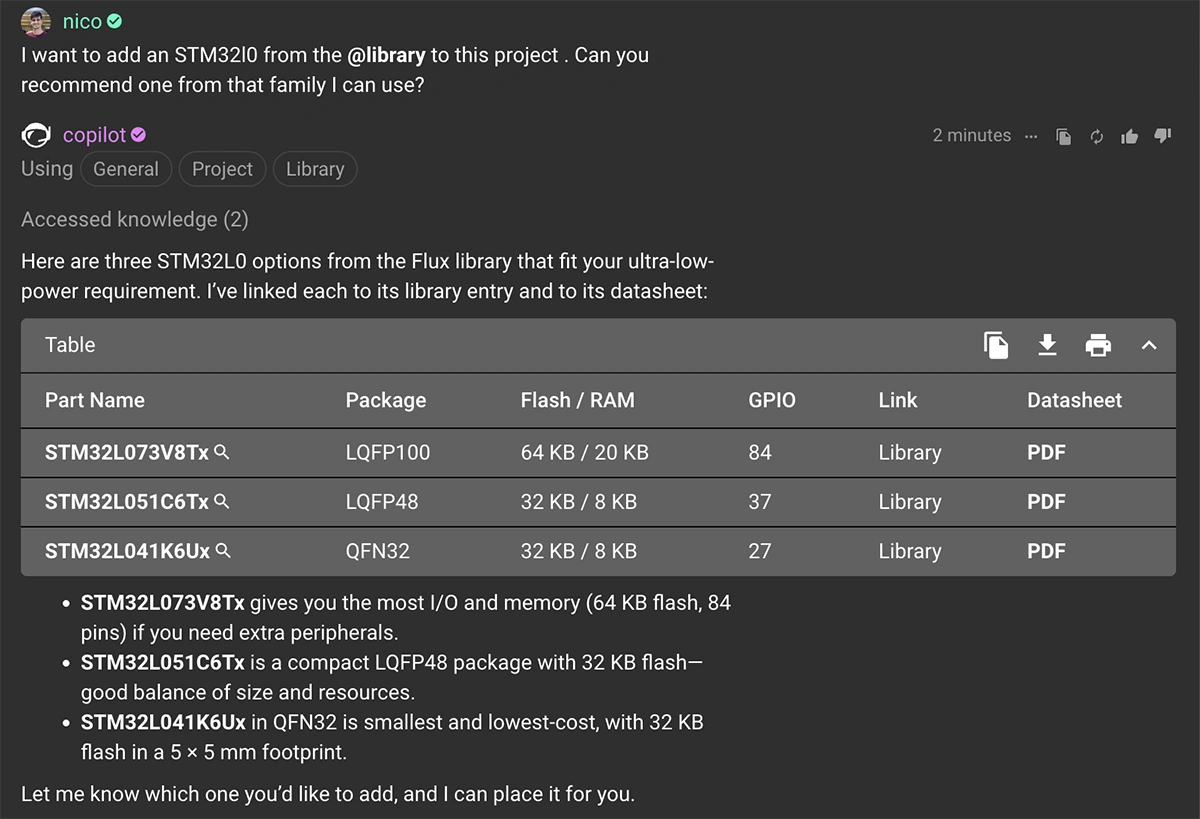
You’ll get a curated set of variants from different vendors, with key spec differences called out and datasheet previews inline. You can quickly assess whether a part meets your requirements, without opening five PDFs.
Context switching kills momentum. You find a part in one tool, then you’re off hunting for its symbol, then toggling over to assign a footprint, then digging through menus just to place it in your schematic. That back-and-forth might not seem like much, but multiply it by dozens of parts, and it adds up fast.
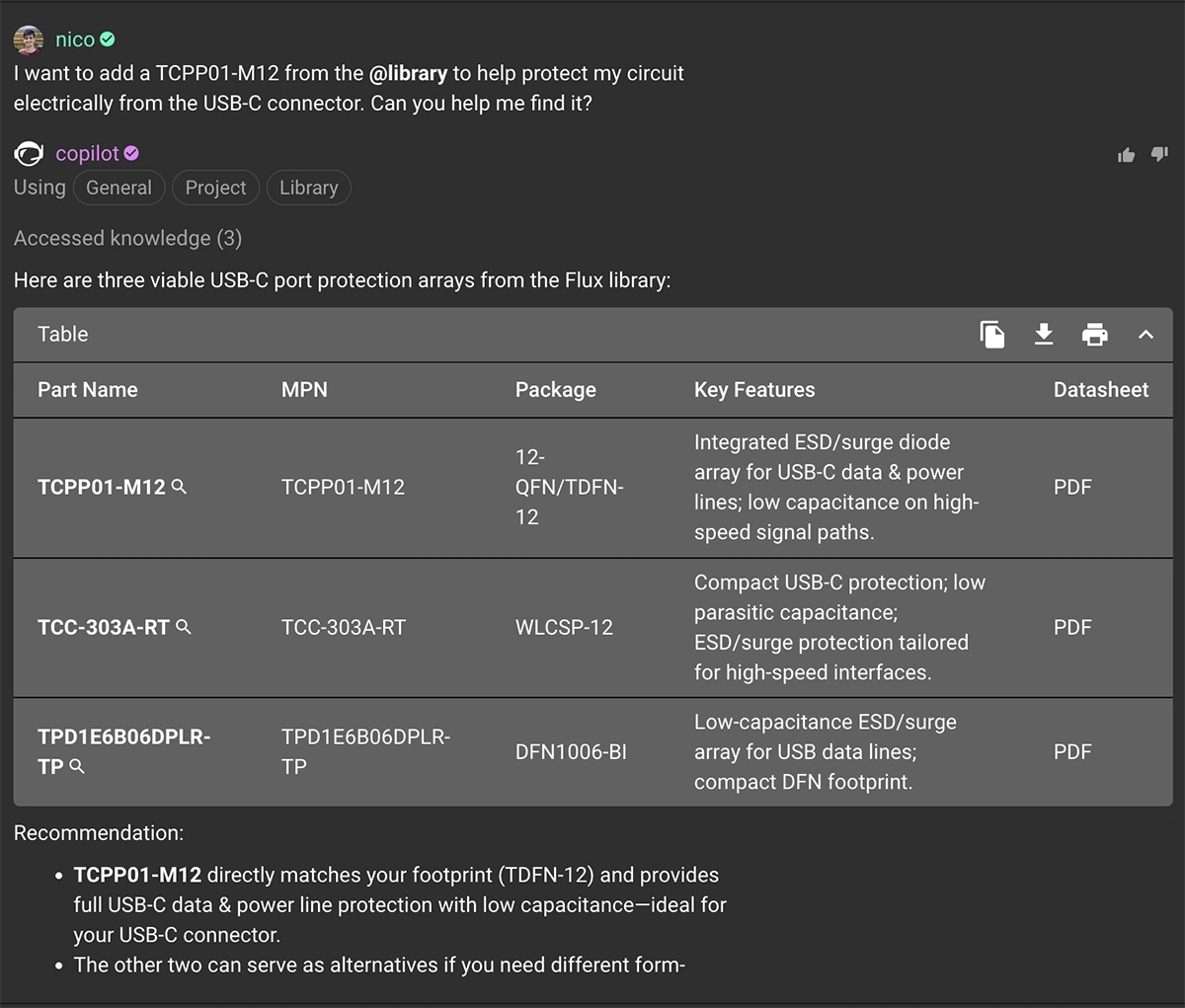
Copilot keeps you in the flow. Once you’ve found the right part, you can take action on it right in the same conversation. Search, validate, and place, all within the same conversation.
Prompt: "I wanto add a TCPP01-M12 from the @library to help protect my circuit electrically from the USB-C connector. Can you help me find it?
You can go from idea to implementation without friction:
Prompt: "Find an MCU for a low-power IoT node."
Prompt: "Place STM32L4R9 in my schematic."
Copilot pulls context-aware results, then places your selection with the right footprint and symbol directly into your schematic. This also works for passives, modules, and more complex components.
Prompt: "Add a resistor divider for a 12V to 3.3V conversion using 1% resistors."
With one thread, you go from requirement → component → placement, all without breaking your flow .
We’ve all been there, clicking through six different datasheets just to confirm one pinout or cross-check a quiescent current value. It’s slow, tedious, and pulls you out of your design flow.
If you're down to two op-amps with nearly identical specs, Copilot can analyze their datasheets and save you 5–10 minutes per part, and help you catch subtle but important differences before committing.
Prompt: "Show me 10 V LDOs under 100 µA quiescent current for battery-powered sensors."
You'll get a table with all the essentials, and you can inspect the PDFs directly, just like you would with tabs and downloads, but without the friction.
What makes this all possible? Behind the scenes, Flux Copilot now uses a combination of two powerful AI strategies: Hybrid Retrieval-Augmented Generation (Hybrid RAG) and an agentic search planning system built specifically for part discovery.
Let’s unpack that.
Hybrid RAG is the foundation, it runs two search engines in parallel:
Copilot fuses both results and re-ranks them based on relevance, so you're more likely to get answers that are both accurate and contextually useful. You don’t need to write the perfect query. Just describe what you need, and Copilot translates it into both a keyword and a semantic search behind the scenes.
But that’s just the starting point.
Copilot doesn’t just run one query and hope for the best. It creates a search plan, executes it, evaluates the results, and adapts, iterating until it finds components that truly match your design intent.
It knows, for example:
This matters because part search isn’t just about finding “a component that works.” It’s about finding parts that fit your schematic, your layout, your budget, and your workflow. And Copilot does that autonomously, in the background, while keeping you in control.
Think of it like designing for both performance and manufacturability. Copilot doesn’t stop at meeting the spec, it helps optimize for the full stack of constraints you care about as a hardware designer.
The result is a part search engine that behaves less like a query box, and more like a teammate who’s thinking alongside you.
The new part search is live now:
As hardware designers ourselves, we built this to remove friction and help you move faster, whether you're validating a quick prototype or heading into production.
Try it out, and if you have thoughts, questions, or edge cases you want to test, we’d love to hear about them in the Flux Slack Community.
This post will give you a deeper understanding of how Flux Copilot works, how large language models (LLMs) and agentic systems operate under the hood, and why grounding them in engineering context matters.
This post will give you a deeper understanding of how Copilot works, how large language models (LLMs) and agentic systems operate under the hood, and why grounding them in engineering context matters. You'll walk away with concrete strategies to get better results — and a clearer sense of how your feedback can shape the future of AI-assisted design.
If you've ever used an AI tool and felt disappointed, you're not alone. Engineers expect precision, and sometimes get something unpredictable. However, that doesn’t mean AI is overhyped. Rather, it means AI is evolving, and we need to learn how to work with it.
AI — especially large language models — is already an incredibly powerful tool. It can synthesize knowledge from thousands of documents, surface insights instantly, and assist in real-time decision-making. But like any tool, it needs to be used correctly. Understanding how it works helps you unlock its full potential.
That’s why we’re writing this. The more you understand how Flux Copilot works under the hood, the more empowered you’ll be to use it effectively, and help shape what it becomes.
At the core of Copilot is a large language model (LLM) — a deep neural network trained on massive datasets to predict the next token in a sequence. In practice, this means it can understand natural language prompts, reason across technical contexts, and generate structured responses.
LLMs aren't "search engines" or "knowledge bases." They don’t retrieve information, they generate it, based on patterns learned during training. This is both their power and their risk: they can generalize across domains and produce fluent output, but they can also produce confident-sounding nonsense — what we call hallucinations.
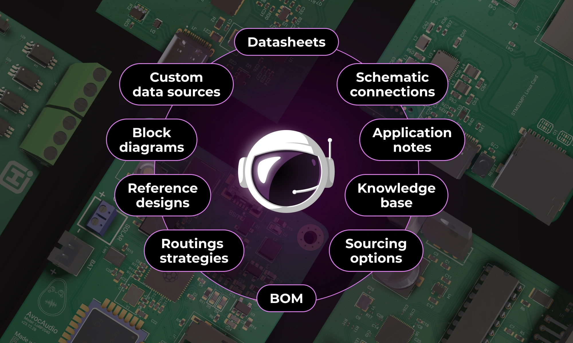
That’s why Copilot isn’t just a raw LLM. It’s an LLM grounded in structured, trustworthy data:
By combining generative reasoning with factual, contextual inputs, we reduce hallucinations and increase the reliability of Copilot’s suggestions. But it's not bulletproof. It can still generate plausible-sounding errors if the grounding data is missing, incomplete, or misinterpreted.
Copilot isn't operating in a vacuum. It's more than just an LLM generating text — it's an AI agent with access to real tools, structured data, and your active design context. Because it understands your schematic — the parts you’ve used, their interconnections, net names, designators, and annotations — it can reason about your design.
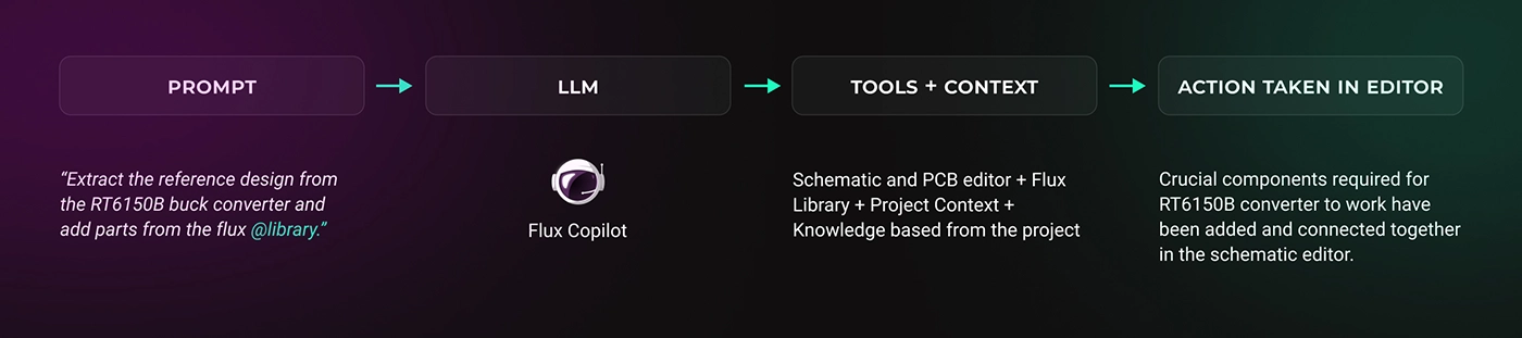
Under the hood, Copilot is connected to a series of tightly integrated tools, each exposing a specific capability:
Together, these tools give Copilot the ability to behave more like a true assistant with systems-level access — not just a text generator.
This kind of functionality bridges the gap between assistant and collaborator. It’s what makes Copilot feel less like a chatbot and more like a teammate. A junior engineer who doesn’t just explain what to do — but starts doing it.
And because Copilot isn’t just responding in a chat bubble — it's connected to your active design — it can take actions: edit the schematic, add components, modify net connections, and flag inconsistencies.
LLMs are generative. They don’t pull facts from a database — they generate answers word by word, based on statistical likelihood. This means they can hallucinate: confidently stating something that sounds plausible but is completely false.
In hardware design, hallucinations can show up as incorrect pin mappings, wrong default values, or oversimplified assumptions. This can lead to real mistakes if the user isn’t validating what Copilot outputs.
While Copilot can take actions inside your project — like editing schematics or inserting parts — some actions may succeed, others may only partially complete, and some prompts might be misunderstood altogether. This is especially true in more complex scenarios, where multiple steps or system-level understanding is needed. The goal is a seamless experience where intent leads to correct execution, but today, users should still expect to guide and verify every step.
Grounding Copilot in real data — through datasheets, project context, and part metadata — helps reduce these risks. But it doesn’t eliminate them. The model might overlook a constraint, misread a spec, or provide a solution that looks reasonable but doesn’t work in practice.
It’s essential to treat Copilot as you would a junior team member: capable, fast, but not infallible. Always review its suggestions. Provide feedback. Ask clarifying follow-ups. That interaction is what turns AI into a truly useful design partner.
We’re also actively working on helping Copilot surface uncertainty — so it can tell you when it’s guessing, and explain what it's basing its answers on (or what information it lacks).
Using Copilot effectively is less about being technical and more about being clear. It’s like working with a new hire who’s smart but unfamiliar with your preferences. The more context you give it, the better it performs.
If you’re looking for a regulator, don’t just say “add an LDO.” Try something like:
“Suggest a 3.3V LDO for an ESP32 with <100uA quiescent current and SOT-23 footprint.”
That level of detail dramatically increases the relevance of the result.
And because Copilot sees your schematic, you can ask things like:
“Which nets are missing decoupling capacitors?”
“Wire up a power tree for these ICs.”
“Add pull-ups to all I²C lines.”
These are tasks that might take you 10–15 minutes. Copilot can do them in seconds — not because it knows better than you, but because it has access to the same information and applies it faster.
You can also refine prompts through iteration. If a response misses the mark, say:
“That’s too high power — optimize for <10mA draw,”
or
“I’d prefer a Texas Instruments part here.”
Copilot remembers the context of your project and previous replies. Treat it like an interactive design partner, not a search engine.
Getting better results with Copilot’s action-taking features — especially for part insertion and wiring — requires a bit of strategy. When asking Copilot to add parts, keep your request scoped to a small, related group of components. For example, instead of saying
“add a power supply,”
try
“Add an 500mA 3.3V linear regulator with a ceramic input capacitor and output capacitors,”
This helps Copilot reason about the function and relationships between components.
Similarly, when wiring things up, ask Copilot to connect two or three components at a time — like wiring up a sensor to a microcontroller with the necessary pull-ups — rather than asking it to connect an entire subsystem in one go. This makes the task more manageable, and improves the accuracy and completeness of the result.
And when it comes to reviewing your work, Copilot can already identify common mistakes, missing components, or inconsistent naming. As we continue building, that design review capability will become even more comprehensive — combining simulation, datasheet validation, and layout context.
Everything we’ve shown so far — contextual understanding, structured reasoning, agentic actions — is just the beginning. The real goal is to make hardware design more fluid, iterative, and collaborative.
We’re building toward a future where describing what you want is enough to begin the design process. Where Flux Copilot understands your intent, accounts for constraints, and takes meaningful steps forward — not just by suggesting, but by executing.
Imagine typing:
“Design a BLE-enabled temperature sensor with 6-month battery life. Optimize for low power.”
And Copilot delivers:
This isn’t sci-fi. It’s the direction we’re actively building toward — and your feedback plays a big role in making it real.
Copilot improves fastest when it’s used by real engineers solving real problems. Here’s how you can help:
Give feedback — What did Copilot do well? Where did it fall short? Be specific.
Train it — Add your naming rules, preferred suppliers, or circuit patterns to Copilot Knowledge.
Push it — Ask for things you wish it could do. Even if it can’t yet, your input helps shape what we build next.
You're not just using a tool. You’re helping define what engineering looks like when AI becomes part of the workflow.
Let’s build it together.
Design high-performance buck converters with proven PCB layout best practices. Cut noise, save space, and optimize your power supply design with this guide.
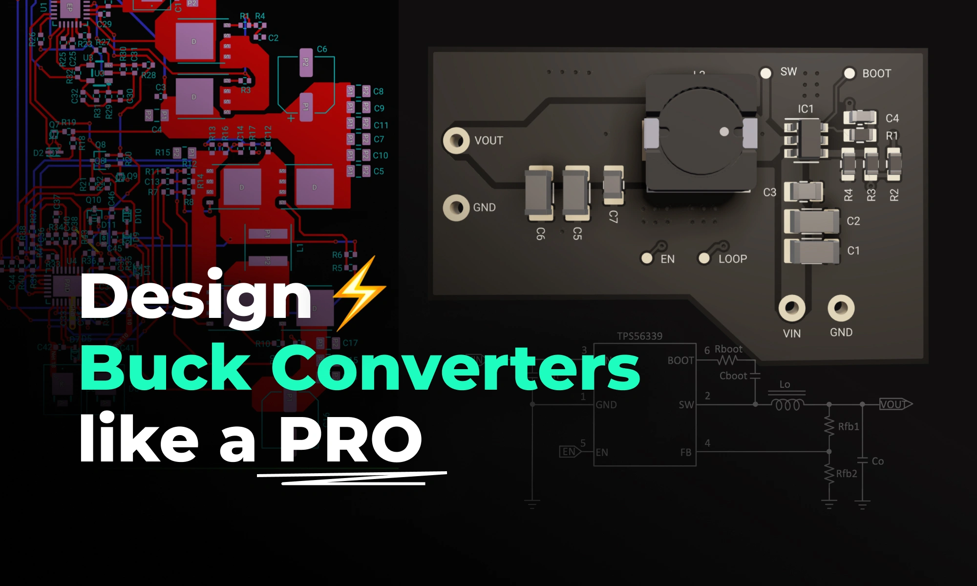
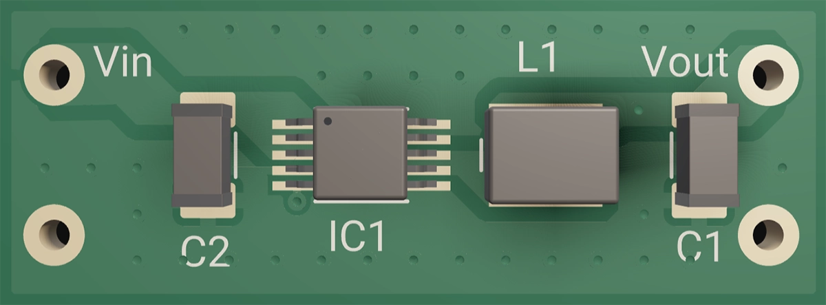
At its heart, a buck converter is nothing more than three core elements working together to regulate a higher voltage to a lower voltage—and understanding these will make everything else click.
Here’s the simple math for a 12 V→5 V converter:
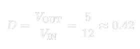
That 42 % duty cycle tells the MOSFET exactly how long to stay on each cycle so the LC filter averages out to 5 V.
Behind the scenes, a control IC monitors the output, compares it to an internal reference, and tweaks that duty cycle in real time to handle changing loads or input swings. But regardless of controller complexity, the switch + inductor + filter always remain the converter’s heart and soul.
Pick the wrong inductor, and you may face problems like overheating, excessive output ripple, or even core saturation that starves your load under sudden demand. To help you choose wisely, here’s what every beginner EE should know about inductor characteristics:
Pro tip: Choosing an inductor with a bit of extra saturation current rating and modestly lower DCR gives you valuable headroom during prototyping—preventing unexpected heat and ripple issues as your load conditions change.
A combination of MLCCs and a bulk cap covers ripple from kHz to MHz—get this wrong, and you’ll hear audible squeals or see output spikes.
Deep dive: MLCCs lose capacitance under DC bias and heat. And yes, they can sing! Ensure parallel MLCCs are carefully secured mechanically to mute piezo effects. Placing smaller-value capacitors first help to attenuate the high frequency singing in the larger smoothing caps.
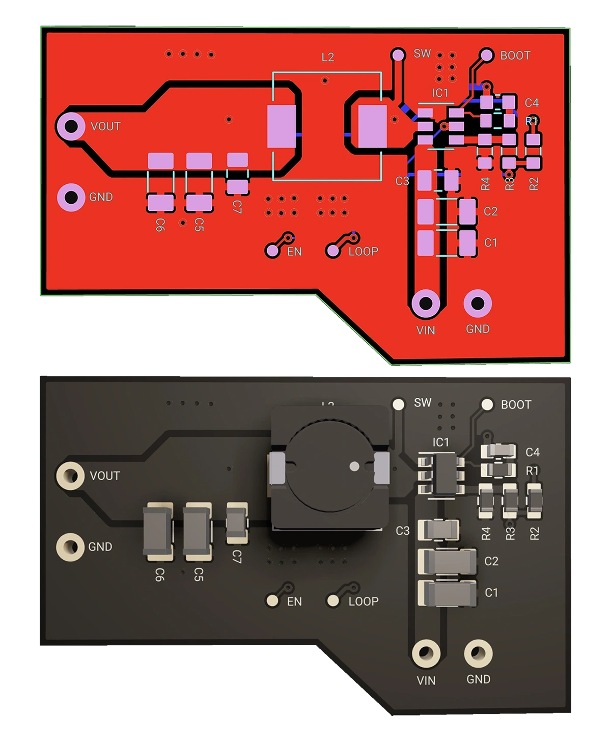
Having chosen your parts, layout is your next battleground. The difference between a noisy, inefficient converter and a clean, reliable one often comes down to copper placement. Follow these steps to keep that switching loop tight and your ground plane unbroken.
Remember: “Keep the switching loop tiny and the ground plane continuous.”
Minimize the Switch Loop
Separate Control Signals
From full DIY assemblies to one-click, ready-to-use modules, these different topologies trade off flexibility, board space, and time-to-market. Pick the one that fits your project rhythm.
Each template already includes polygon pours for power and ground, and via-stitching. Once cloned, customize only what matters.
Ground planes are a default in any Flux project, which reflows around all parts and pads to help with noise isolation. Polygons are now in Flux helping you leverage wide current paths for your output voltage to flow through. Adjust thermal reliefs, keep-outs, and copper weights without redrawing anything.
🤖 Copilot: Your AI EE Mentor:
Stuck on compensation loops or gate-resistor values? Ask Copilot right inside the editor. It explains theory, suggests values, and even pulls tables from datasheet PDFs.
🛣️ Auto-Layout for Non-Critical Nets:
Zone off low-speed signals—UART, I²C, sensors—and let Auto-Layout handle them. That frees you to hand-route the critical buck loops that define performance.
“Copilot help me determine the best orientation of U1 to minimize the switching current loop.”
Think of this as your design checklist: tape it to your monitor, keep it next to your keyboard, or fold it in your notebook. Pull it up whenever you need a formula, a layout reminder, or a topology refresher.
With Flux’s polygons, AI Copilot, and Auto-Layout, you’ll spend less time wrestling nets and more time optimizing your power stage—so you can ship faster and with confidence.
👉 Get started now » Open Flux and Clone a Buck Converter