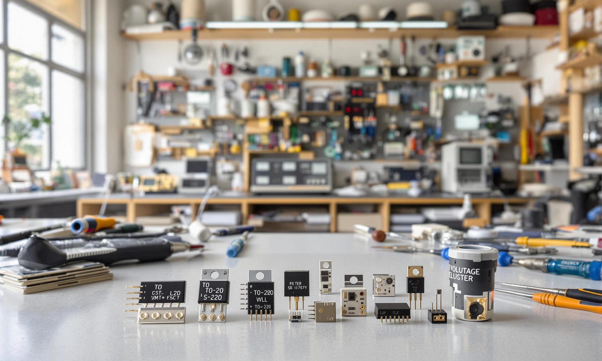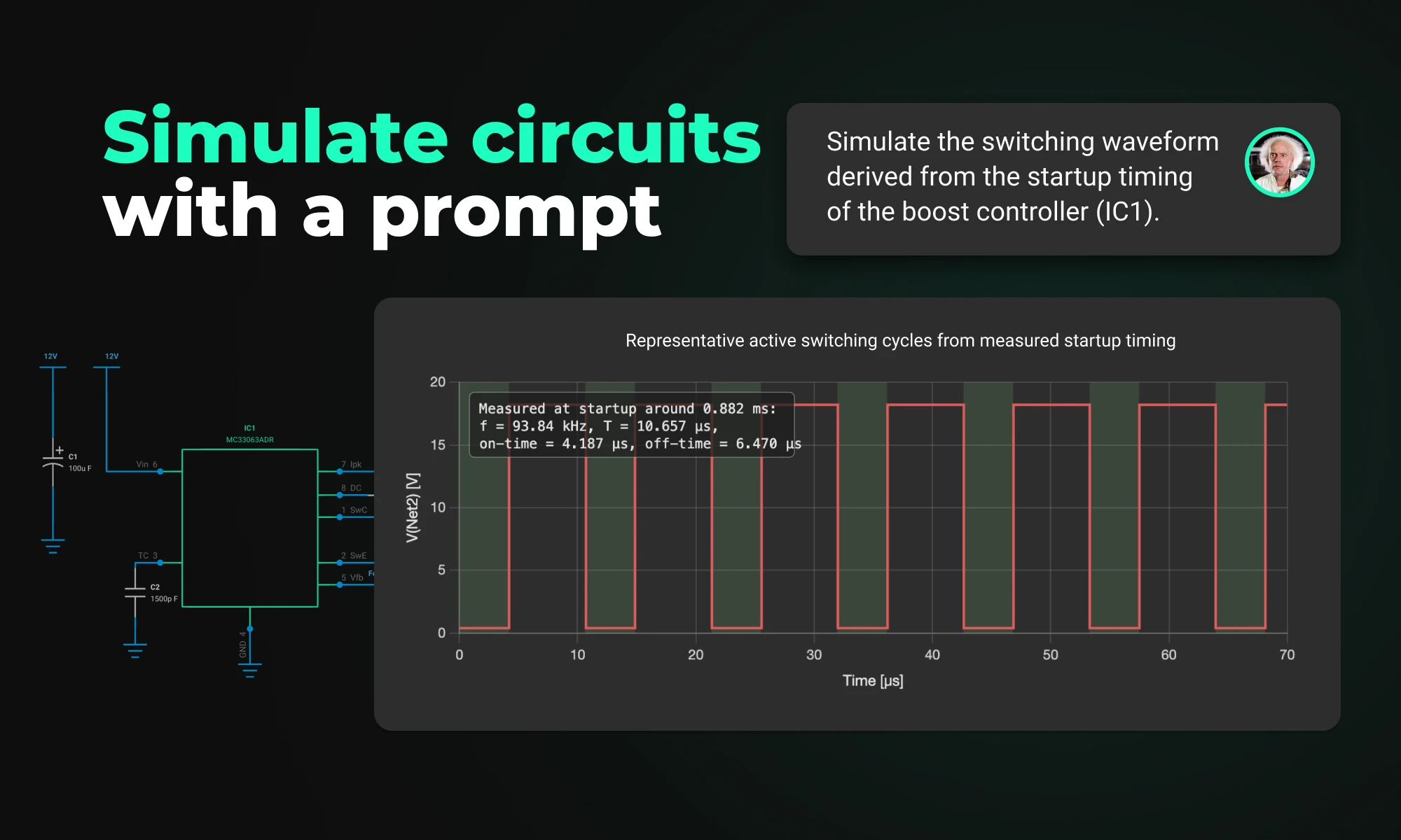
Flux brings circuit simulation to wherever you are in the design process. Start from a prompt when you have no schematic, or let Flux analyze your existing design automatically.

Voltage regulators ensure stable power in electronics. This post covers types, uses, and selection tips—plus how AI tools like Flux.ai streamline design.
A voltage regulator is your circuit's guardian, maintaining a constant output voltage despite input fluctuations or load changes. This stability is essential because most electronic components operate within specific voltage ranges. Too much voltage can damage components or reduce their lifespan. Too little can cause malfunctions or complete failure. As Wikipedia explains, a voltage regulator is "a system designed to automatically maintain a constant voltage."
Let's explore how these devices work, the different types available, and how to select the right one for your application. Next, we'll dive into operation principles, regulator types, key applications, selection criteria, and troubleshooting tips.
At its core, a voltage regulator works through a feedback control mechanism. The system constantly compares the output voltage to a fixed reference voltage. When it detects a difference, it adjusts to bring the output back to the desired level.
The main components include:
When input voltage rises, the regulator reduces conductivity through the pass element. When input voltage drops, it increases conductivity. This dynamic response maintains stable output even during significant input fluctuations.
Linear regulators work like a variable resistor, continuously adjusting to maintain the desired output voltage. They're the simplest type of regulator and operate by dissipating excess voltage as heat.
Advantages:
Drawbacks:
Common examples include the 78xx series (like the 7805 for 5V output) and Low-Dropout (LDO) regulators that can operate with minimal voltage difference between input and output.
Switching regulators use a different approach. They rapidly switch a pass element on and off, storing energy in inductors or capacitors during the "on" phase and releasing it during the "off" phase.
These come in three main topologies:
Switching regulators achieve much higher efficiency (often 85-95%) than linear regulators. This makes them ideal for battery-powered devices and high-power applications. But they generate more noise and require more components.
AI-driven layout tools, such as Flux AI's Auto-Layout, offer advanced capabilities to significantly enhance the design process by optimizing trace flows. These tools utilize artificial intelligence algorithms to analyze and arrange circuit layouts in a way that minimizes electromagnetic interference (EMI). By intelligently routing traces, AI-driven layout solutions help reduce noise and signal degradation, leading to improved overall performance and reliability of electronic devices.
Shunt regulators divert excess current away from the load to maintain a stable voltage. The TL431 programmable precision shunt regulator provides a 2.5 V reference and allows adjustable output via two resistors—ideal for precision reference and over-voltage protection.
Digital or programmable regulators allow output voltage adjustment through digital interfaces. These modern regulators often include additional features like telemetry feedback and fault reporting.
Voltage regulators are everywhere in modern electronics:
When selecting a voltage regulator, consider these factors:
Don't forget to check our Documentation and join the Slack Community for design tips and peer support.
Voltage regulators are the unsung heroes of electronics—protecting components, ensuring steady performance, and extending lifespan. By mastering their principles, comparing types, and following best practices, you'll build rock-solid systems. And with Flux.ai's browser-based, no-install platform—featuring AI Auto-Layout (learn more), Flux Copilot for on-the-fly component recommendations, multi-MCU support, collaborative editing, and seamless documentation (docs)—you can design, verify, and iterate faster than ever. Ready to optimize your next power regulation circuit with AI assistance? Visit flux.ai today!
This guide explores toggle switches, their types, and applications in electronics. Learn how they work and find the right one for your project.
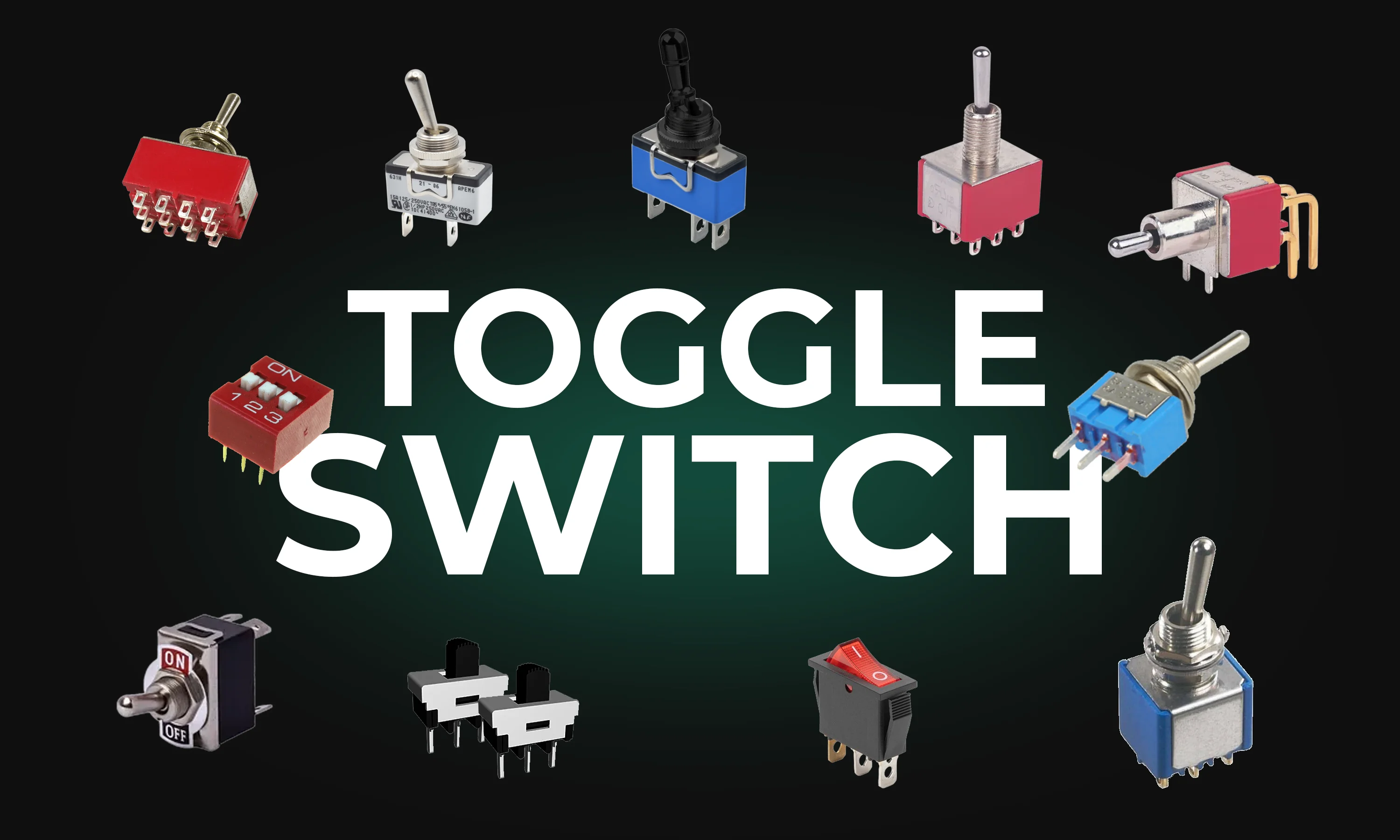
A toggle switch is a mechanical device that opens or closes an electrical circuit by moving a lever back and forth. It is named after its characteristic toggle action, which makes a definitive "on" or "off" position. Toggle switches come in various designs and configurations to suit different applications.
There are several types of toggle switches, each designed for specific functions and environments. Here are the most common types:
Toggle switches are used across various industries and applications, including:
The working mechanism of a toggle switch is straightforward:
Some advanced toggle switches also include LED indicators or built-in resistors for enhanced functionality.
When selecting a toggle switch for your project, consider the following factors:
Toggle switches are indispensable components in electrical and electronic systems. Their versatility, ease of use, and variety of configurations make them ideal for countless applications. By understanding the types, uses, and selection criteria, you can confidently choose the right toggle switch for your project, whether it's a simple DIY circuit or an industrial control system.
Understanding amps and volts is key to working with electronics. This guide explains their roles, relationship, and practical applications.
Amps, short for amperes, measure electrical current—the flow of electric charge through a conductor. Think of current as the rate at which electrons move in a circuit. More amps mean more electrons are flowing per second.
For example:
Volts measure electrical potential difference or "pressure" in a circuit. It’s the force that pushes electrons to move through a conductor. Higher voltage means greater potential to drive electrical current.
For example:
Amps and volts are interdependent and linked by Ohm's Law, which is fundamental in electronics:
Ohm’s Law: V = I * R
Where:
This means:
One of the best ways to visualize amps and volts is to compare electricity to water flowing through a pipe:
Higher water pressure (voltage) pushes more water (current) through the pipe, but if the pipe is narrow (high resistance), less water flows regardless of the pressure.
Here are some common scenarios where understanding amps and volts is helpful:
Understanding the difference between amps and volts is essential for anyone working with electronics or electrical systems. Amps measure the flow of current, while volts measure the force driving that flow. Together, they determine how electricity powers devices. By grasping their relationship and practical applications, you'll be better equipped to design circuits, troubleshoot issues, and choose the right components for your projects.
This blog explores the powerful Arduino map() function, showing you how to scale values, control sensors, and master advanced programming techniques for innovative projects.
The Arduino map() function is a versatile and widely used tool for scaling numbers from one range to another. Whether you're a beginner or an experienced Arduino enthusiast, understanding how this function works and how to use it effectively is crucial for optimizing your projects. In this blog, we’ll cover everything from what the map() function does to practical examples and advanced tips for its use.
map() Function?At its core, the map() function takes an input number within a specific range and maps it to an output number within a different range. This is especially useful when working with sensors, where raw data needs to be converted into meaningful values like temperature, distance, or percentage.
The syntax for the map() function is straightforward:
The function calculates the mapped value using this formula:
map() Function?In Arduino projects, raw sensor data often needs to be scaled for meaningful interaction. For example:
Using the map() function simplifies your code and reduces errors that can arise from manually calculating scaled values.
A common use case for the map() function is reading the input from a potentiometer and converting it to a different range. Here’s an example:
This code reads the raw analog value from a potentiometer and maps it to a percentage (0-100%). This is ideal for applications where you want to control brightness, volume, or other scaled parameters.
map() FunctionServo motors usually operate within a range of 0 to 180 degrees. If you're using a joystick with an analog output, you can map its range (0-1023) to match the servo's range:
The map() function can be used to adjust the brightness of an LED using PWM. Here’s an example:
map() FunctionHandle Out-of-Range Values: The map() function does not automatically constrain input values to the defined range. For safety, you can use the constrain() function:
Floating-Point Mapping: The map() function only works with integers. For floating-point precision, you can implement a custom version:
Inverse Mapping: You can reverse the input and output ranges to invert the mapping. For example, map 0-1023 to 255-0 for inverting brightness:
map()map() for Nonlinear Scaling: The map() function only provides linear scaling. For exponential or logarithmic scaling, you need custom formulas.The Arduino map() function is a simple yet powerful tool that enhances the flexibility and functionality of your projects. From controlling servos to scaling sensor data, its applications are vast and varied. By mastering its use and understanding its limitations, you’ll be well-equipped to handle a wide range of Arduino projects.
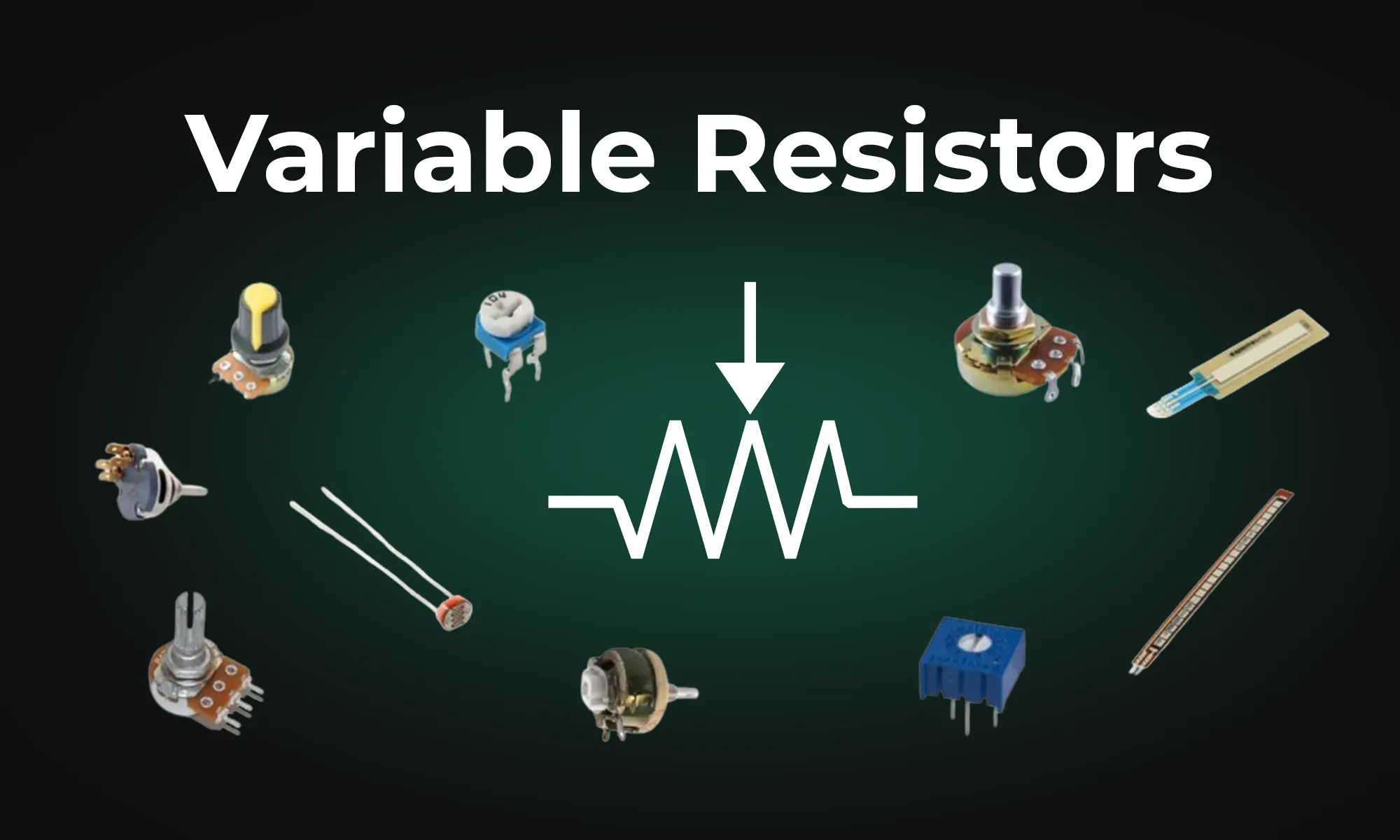
This article provides an overview of six types of variable resistors, including potentiometers, rheostats, photoresistors, wirewound resistors, thermistors, and varistors, highlighting their unique uses in electronic circuits. It also covers advanced applications and emerging technologies like digital potentiometers and memristors, emphasizing their significance in electronic control and adaptability.
Potentiometers, often referred to as "pots," enable fine control of resistance by using a dial or sliding element. The resistive element of a potentiometer can be adjusted using a wiper, controlled by turning a knob. Along with the “wiper” terminal, potentiometers have two additional terminals, typically referred to as “input” and “output” terminals. Two common types of potentiometers are linear and rotary. Linear potentiometers find use in applications like volume control on audio devices, while rotary potentiometers are employed in settings requiring rotational adjustment, such as tuning radio frequencies. They come in various forms, including carbon film and metal oxide variants.
Rheostats are specialized variable resistors designed with only two terminals. While potentiometers are used to control voltage, the primary use of rheostats is to control current in a circuit, adjusting electrical resistance as needed. The two terminals are connected in series with a load (e.g., a light bulb or motor). Adjusting the position of a wiper along the resistance wire changes the resistance in series with the load, thus controlling the current. Common applications of rheostats include dimmer switches for lights and motor speed control.
Photoresistors, also known as light-dependent resistors (LDRs), are two-terminal resistors that change in response to light levels. An LDR exhibits a decrease in resistance as light intensity increases, enabling it to sense and react to environmental light changes. This property makes an LDR ideal for applications like automatic lighting control and light-sensitive alarms.
Wirewound resistors, constructed by winding a resistive wire around an insulating core, are known for their precision and ability to handle high power levels. Although having both fixed and variable variations, variable wirewound resistors allow for the length of the resistance wire included in the circuit to change, altering the resistance. Wirewound resistors also have two terminals. Wirewound resistors are used in applications that demand precise resistance values, such as in precision instruments and high-power electronic circuits.
Wirewound resistors come in both precision and power varieties. Precision wirewound resistors offer high accuracy and low tolerance, making them suitable for applications like voltage dividers and precision amplifiers. Power wirewound resistors are built to withstand high power levels, ensuring they can maintain their resistor value under challenging conditions, making them suitable for high-current circuits and power amplifiers.
Thermistors are temperature-sensitive resistors with two terminals that exhibit changes in electrical resistance with temperature fluctuations. They are classified into two primary types: negative temperature coefficient (NTC) and positive temperature coefficient (PTC). NTC thermistors decrease resistance with increasing temperature, while PTC thermistors exhibit the opposite behavior, making them essential in temperature control systems, such as thermostats, and are vital for temperature compensation in various electronic circuits.
Varistors, also known as voltage-dependent resistors or VDRs, are specialized two-terminal variable resistors designed to protect electronic circuits from voltage spikes and surges. They exhibit a high electrical resistance under normal conditions but rapidly decrease their resistance when exposed to excessive voltage. This behavior allows varistors to shunt excessive voltage away from sensitive components by allowing high current to flow through the varistor instead. Varistors find use for surge protection in electronic systems.
To provide a quick reference, here's a table summarizing these six types of variable resistors:
Voltage dividers are circuits that divide an input voltage into smaller output voltages usually using resistors. Variable resistors, and especially potentiometers, are useful components in creating variable voltage divider circuits. By adjusting the resistance, you can finely control the output voltage.
Variable resistors are at the heart of electronic control and adaptability, and understanding their diverse types and applications is a vital step toward becoming proficient in electronics.
The blog post dives into the technical aspects of Multilayer Ceramic Capacitors (MLCCs), highlighting their importance in electronic circuits. It explains the construction of MLCCs, where layers of ceramic material and metal electrodes create a multilayered structure to store electrical energy.
At its core, a multilayer ceramic capacitor is a passive component that stores electrical energy in an electric field. Its construction involves layers of ceramic material, typically composed of barium titanate, sandwiched between metal electrodes. These layers, when stacked, create a multilayered structure, hence the name.

The dielectric material used in MLCCs significantly influences their performance and Capacitance–which can range from a few picofarads to several microfarads. This flexibility in capacitance makes MLCCs versatile components that can be tailored to meet the diverse needs of electronic circuits. Common dielectric materials include C0G, X7R, and X5R, each offering distinct properties that cater to specific applications.
C0G, also referred to as NP0, is a dielectric material that contributes to the stability of multilayer ceramic capacitors (MLCCs). C0G is a class I dielectric material. The primary composition of C0G dielectrics is typically a mix of finely ground paraelectric materials. The most common material used is titanium dioxide (TiO2), which is often mixed with additives like magnesium titanate (MgTiO3) or calcium titanate (CaTiO3). These materials are chosen for their stable electrical properties and minimal variation in capacitance with temperature.
Temperature Coefficient of Capacitance (TCC): C0G MLCCs are renowned for their minimal temperature coefficient of capacitance (TCC). The TCC of C0G is near-zero, signifying that the capacitance remains nearly constant across a wide temperature range, making C0G capacitors ideal for stable capacitance under the required temperature.
C0G has minimal dependence on applied voltage. This ensures that the capacitance remains consistent even under varying voltage levels.
C0G capacitors exhibit low dielectric losses, indicating minimal dissipation of electrical energy as heat, crucial for applications where efficiency and signal integrity are critical.
X7R and X5R are dielectric materials widely used in MLCCs, offering a balance between versatility and size efficiency. X7R and X5R are class II dielectrics. These materials are predominantly based on a ferroelectric material, barium titanate (BaTiO3). To achieve the desired dielectric properties, various dopants and additives are introduced, such as magnesium oxide (MgO), yttrium oxide (Y2O3), and zirconium oxide (ZrO2). The addition of these dopants helps in modifying the grain structure and electrical properties of the barium titanate, tailoring it for specific capacitance and temperature coefficient requirements. X7R and X5R materials are engineered to offer a compromise between high capacitance values and stability over a broad temperature range.
While not as temperature-stable as C0G, X7R and X5R materials are well-suited for applications where a balance between size, cost, and performance is essential.
The incorporation of additives in X7R and X5R dielectric materials allows these capacitors to achieve higher capacitance values in smaller physical sizes. This is advantageous for applications where space efficiency is a priority, and a higher capacitance is required.
X7R MLCCs find widespread use in applications where a balance of size, capacitance stability, and cost-effectiveness is crucial. Common applications include power supply filtering, coupling and decoupling, and general-purpose signal conditioning.
These capacitors are commonly employed in consumer electronics, such as smartphones and tablets, where space constraints and performance are equally critical.
In environments demanding precision and stability, C0G MLCCs shine. These capacitors are often chosen for high-frequency applications, RF circuits, and critical timing elements where deviations in capacitance can have significant repercussions on performance.
Multilayer ceramic capacitors are available in both leaded and surface-mount device (SMD) configurations. Leaded MLCCs have protruding leads for through-hole mounting, offering ease of manual assembly. SMD MLCCs are designed for automated assembly processes, contributing to the miniaturization of electronic devices.
While MLCCs dominate the capacitor landscape, tantalum capacitors deserve a mention. Tantalum capacitors offer high capacitance density and reliability, making them suitable for applications where space is at a premium and extended operational life is crucial.
The dielectric material used in an MLCC is a critical factor influencing its performance. Engineers must carefully consider the trade-offs between precision, size, and temperature stability when selecting C0G, X7R, or X5R variants.
ESR is a measure of the opposition a capacitor presents to the flow of alternating current. Low ESR is crucial in applications where high-frequency performance is paramount, such as in power supply decoupling.
Leaded MLCCs offer simplicity in manual assembly, while SMD variants contribute to automated assembly processes, enabling efficient mass production.
Researchers are actively exploring methods to increase the capacitance density of MLCCs. One avenue of exploration involves advancements in materials engineering, seeking new dielectric formulations to push the boundaries of capacitance values with an emphasis on maintaining stability across a broad temperature range. Additionally, researchers are investigating techniques to optimize the stacking of ceramic layers within MLCCs, aiming for more efficient use of space without sacrificing performance.
Additive manufacturing, such as 3D printing of capacitors, is being investigated for its potential to create intricate structures that optimize electrical properties.