February 21, 2024
What Is a Functional Block Diagram and Why Is It Critical in System Design
Share

A functional block diagram is a schematic representation that delineates the principal functions of a system and the flow of data between them. It serves as a cornerstone in system engineering, simplifying the visualization of complex interactions within systems. FBDs are characterized by their use of labeled blocks connected by lines indicating dataflow, making them an intuitive means for depicting system operations.
The advantages of function block diagrams are that they’re very easy to follow and understand. They are generally laid out to mimic a specific process thus making it easy to understand for those who don’t have a background in plc programming.
In essence, an FBD breaks down large systems into manageable, functionally discrete blocks, facilitating a modular approach to system design. This modularity is crucial, allowing designers to focus on individual functions without being overwhelmed by the system's overall complexity.
The potency of a functional block diagram lies in its simplicity and clarity, achieved through three fundamental components:
FBDs do not exist in isolation; they are part of a larger ecosystem of programming languages and representation techniques used in the programming of programmable logic controllers (PLCs). Ladder logic, with its origins in electrical wiring diagrams, offers a graphical method that is intuitive for those with a background in electrical engineering. It depicts control logic in a format resembling a ladder, with rungs representing logical operations.
Structured text, another facet of PLC programming, is a high-level textual programming language that resembles traditional computer programming languages. It allows for complex instructions and algorithms to be implemented in a more familiar syntactic form.
FBDs complement these programming paradigms by providing a visual overview of system logic and dataflow, serving as a bridge between the conceptual design and the detailed implementation in ladder logic or structured text. This synergy enhances the understandability, development efficiency, and maintainability of PLC-based systems.
PLCs stand at the forefront of industrial automation, controlling machinery and processes with precision and reliability. In the domain of PLC programming, FBDs play a pivotal role, offering a graphical method for designing and implementing control logic.

FBDs align perfectly with the operational paradigm of PLCs, which are inherently designed to execute logic operations based on real-time data inputs. The visual nature of FBDs facilitates the rapid development and troubleshooting of PLC programs, enabling engineers to map out complex control strategies in a more intuitive and less error-prone manner.
Moreover, the adoption of FBDs in PLC programming underscores the importance of a clear and structured approach to system design. By visualizing the functional architecture of a system, engineers can ensure that all components interact harmoniously, leading to more robust and reliable PLC-based control systems.
As system complexity continues to escalate, the role of functional block diagrams in system design is not only preserved but also expanding. The integration of FBDs with advanced simulation tools and software development environments is enhancing their utility, allowing for more dynamic and interactive system modeling.
The future of FBDs is likely to witness further integration with artificial intelligence and machine learning technologies, enabling smarter and more adaptive systems. As these advanced systems become more prevalent, the clarity and efficiency offered by FBDs will become even more critical in navigating the complexity of modern system design.
Functional block diagrams are a testament to the power of visual representation in the realm of system design. By distilling complex system functionalities into comprehensible blocks and illustrating the dataflow dynamics, FBDs provide a foundation for designing, implementing, and maintaining sophisticated systems. Their symbiotic relationship with ladder logic, structured text, and PLC programming languages enhances their utility, making them an indispensable tool in the engineer's toolkit.


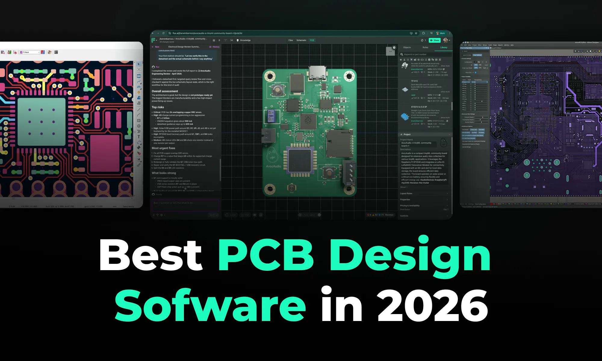
A 2026 comparison of the top PCB design tools — Flux, Altium Designer, KiCad 10, and Fusion 360 — covering usability, features, collaboration, pricing, and the shift toward cloud-native, AI-assisted workflows.

A beginner-friendly guide to electronic circuit design, walking through schematics, key components, the schematic-to-PCB workflow, and how modern collaborative tools speed up hardware development.
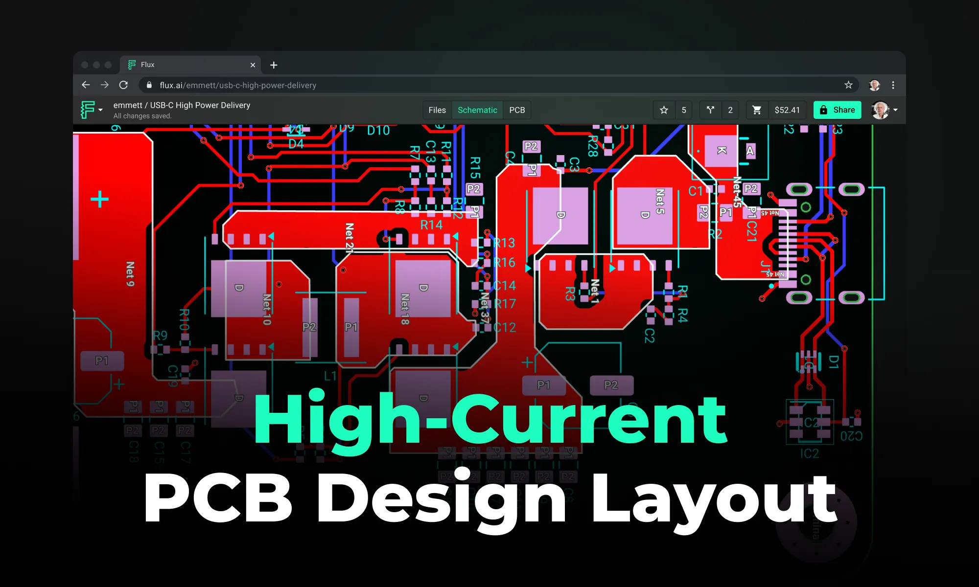
A practical guide to high-current PCB design, covering trace width and copper weight, thermal management with vias and copper pours, layout best practices, and common mistakes to avoid in power electronics boards.

A guide to choosing PCB materials, comparing standard FR4 with advanced substrates like Rogers, PTFE, polyimide, and ceramics, and explaining how dielectric, thermal, and mechanical properties affect performance.

A practical guide to calculating PCB trace resistance, covering the core formula, how geometry affects resistance, worked examples, and design tips to minimize voltage drop and heat.

A practical guide to diagnosing and fixing PCB failures, covering common symptoms, a step-by-step debugging workflow, essential tools (multimeter, oscilloscope, logic analyzer, thermal camera), a pre-power-up checklist, and the design mistakes that most often lead to broken boards.

A practical guide to PCB impedance control, covering why it matters for signal integrity, the four physical variables that shape trace impedance, and how to enforce impedance targets from stackup planning through routing and fabrication.

A practical guide to reducing EMI in PCB design through grounding, return path control, shielding, and layout best practices. Covers EMC compliance with CISPR 32 and FCC Part 15.
