September 14, 2023
LM741 Pinout: A Deep Dive into a Classic Op Amp
Share

Before we dive into the pinout, let's clarify what an op amp is. An operational amplifier is a type of amplifier that takes a voltage input and provides an amplified voltage output. The degree of amplification is determined by the circuit configuration and the external components connected to the op amp. Now that we've set the stage, let's explore the pinout diagram of the LM741.
Understanding the pinout of an integrated circuit like the LM741 is crucial for proper application. A pinout diagram visually represents the functions of each terminal or pin on the IC. The LM741 typically comes in a Dual In-Line Package (DIP), but it is also available in SOIC (Small Outline Integrated Circuit) form. Whether you're looking at a DIP or SOIC package, the pinout remains nominally the same.
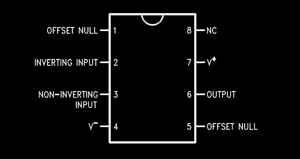
One of the first things to note on the LM741 pinout diagram are the inverting and non-inverting inputs. The inverting input is where the signal to be amplified is often fed when you're building an inverting amplifier circuit. Conversely, if you're designing a non-inverting amplifier, you'll use the non-inverting input.
The LM741 pinout also includes terminals for connecting the positive and negative voltage supplies (V+ and V-), essential for the amplifier's operation. Always consult the datasheet, often found on a .org or .com website, for the recommended voltage levels.
The offset null pins are used for offset voltage adjustment, critical in applications that require high precision. Offset is the dc voltage difference between the inverting and non-inverting inputs when the output is nominally zero volts.
The output pin provides the amplified voltage signal. Depending on the circuit configuration, the output can be in phase or out of phase with the input.
The LM324 is another popular opamp often considered alongside the LM741. While both are operational amplifiers, the LM324 has four opamps in a single IC, compared to the single opamp in an LM741. This allows for more flexibility in circuit design but complicates the pinout slightly.
You can use the LM741 in a variety of circuit applications, not just as an amplifier. For instance, it can function as a voltage comparator. A comparator takes two voltage inputs and outputs a voltage indicating which input is higher. In this role, the LM741 offers less precision than dedicated comparators but is often sufficient for simple tasks.
So there you have it, a comprehensive look at the LM741 pinout and its many applications, from its use as an amplifier to a comparator. This IC is not just a basic operational amplifier but a versatile component suitable for a wide range of voltage amplification and comparison tasks. Whether you’re a seasoned engineer or just starting out, the LM741 remains an essential tool in your electronics toolkit.
Remember, before plugging anything in, always refer to the pinout diagram and other resources from trusted .org or .com websites to ensure you're connecting everything correctly. Happy building!


ERC checks schematic-level electrical issues while DRC checks PCB layout rules -- engineers run ERC before layout and DRC during or after routing.

The complete hardware design workflow covers requirements, schematic capture, PCB layout, validation, prototyping, and manufacturing.

PCB constraint management defines routing, spacing, impedance, and manufacturing rules and validates them throughout PCB layout.

PCB revision management tracks what changed, who changed it, and why -- keeping schematics, layout, BOM, and manufacturing files aligned.

PCB symbol design directly impacts how fast a team can interpret a circuit, spot errors, and generate an accurate netlist.

Real-time PCB collaboration allows multiple engineers to review, edit, and manage PCB designs in a shared environment, reducing version confusion and speeding reviews.

Common schematic design mistakes include unclear labeling, missing power connections, inconsistent symbols, unconnected pins, poor organization, and skipping ERC.

How hardware teams apply Git-style version control to PCB design — tracking revisions, collaborating safely, and maintaining a complete design history.
