Connectors
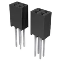
A connector is a device that is used to join two or more electrical or mechanical components. Connectors are an essential part of many electronic and mechanical systems, as they allow for the easy transfer of electricity, data, or other signals between different devices or components. There are many different types of connectors, each designed for specific use cases. Some common use cases for connectors include: * Connecting electronic components in circuit boards * Connecting electrical devices to power sources * Connecting mechanical components in machines and devices * Connecting data cables for networking and communication * Connecting audio and video components in home theater systems Flux.ai has the world's largest community-driven public library of connectors, with footprints, symbols, datasheets, and simulation models. This library is a valuable resource for engineers and designers who need to find and use connectors in their projects.
2479774-2
USB-C (USB TYPE-C) Receptacle Connector 24 (6+18 Dummy) - Power Only 6 Pin Position Surface Mount, Right Angle; Through Hole The 2479774-2 specification defines the engineering requirements for a high-density electronic connector assembly intended for board-to-cable or board-to-board interconnection in advanced electronic systems. This specification establishes the functional, mechanical, electrical, environmental, and quality requirements necessary to ensure reliable signal transmission, stable mechanical engagement, and long-term durability in demanding electronic applications. The component is intended for use in systems requiring compact interconnect solutions with high signal integrity and robust mechanical retention. It is suitable for applications such as industrial electronics, communication systems, embedded control units, and high-performance electronic assemblies where reliable connectivity and repeatable mating performance are required. Engineering Requirements The connector assembly shall be manufactured using precision-formed conductive materials and high-strength insulating housing materials to ensure stable electrical performance and mechanical reliability. The design shall support secure mating engagement and consistent signal continuity across repeated connection cycles. Electrical characteristics shall ensure low contact resistance, stable signal integrity, and reliable conductivity under defined operating conditions. The connector shall maintain performance under mechanical vibration, thermal variation, and environmental stress conditions typical of industrial and embedded system applications. Mechanical construction shall ensure accurate alignment between mating interfaces, secure locking engagement, and resistance to accidental disconnection. The design shall support repeated mating cycles without degradation of electrical or mechanical performance. Workmanship shall be free from defects such as contamination, deformation, plating irregularities, or structural inconsistencies that could impact reliability or functionality. Manufacturing and inspection shall be conducted under controlled quality systems using calibrated equipment to ensure compliance with engineering requirements. Any deviation from this specification shall require formal engineering review, documented justification, and approval through established engineering change control procedures prior to implementation. Documentation Supporting documentation shall include engineering drawings, connector datasheets, material declarations, inspection records, qualification test reports, and revision-controlled manufacturing documentation. All documentation shall be maintained under formal configuration management and quality assurance systems. Revision Control All changes to this specification shall be managed through formal engineering change control procedures. Each revision shall undergo technical evaluation, validation, and approval prior to release to ensure continued compliance with design intent and applicable standards. #EngineeringSpecification #Connector #HighDensityInterconnect #ElectronicComponents #SignalIntegrity #EmbeddedSystems #IndustrialElectronics #Manufacturing #QualityAssurance #EngineeringDocumentation
4 Uses0 StarsFH12S-45S-0.5SH(55)
45 Position FFC, FPC Connector Contacts, Bottom 0.020" (0.50mm) Surface Mount, Right Angle The FH12S-45S-0.5SH(55) specification defines the engineering requirements for a fine pitch flexible printed circuit and flexible flat cable connector designed for compact electronic assemblies requiring high density signal interconnection. This specification establishes the mechanical, electrical, environmental, and quality requirements necessary to ensure reliable signal transmission, stable mechanical retention, and consistent performance in board-to-cable interconnect applications. The component is intended for use in electronic systems where space-constrained design and high pin density interconnection are required, such as display modules, embedded control systems, and portable electronic devices. It provides a secure mating interface for flexible cables while maintaining low contact resistance and stable signal integrity under mechanical and environmental stress. Engineering Requirements The connector shall be manufactured using high-quality insulating materials and precision-formed metal contacts to ensure consistent electrical continuity and mechanical reliability. The design shall provide a secure locking mechanism suitable for repeated mating cycles without degradation of contact performance. Electrical characteristics shall support stable signal transmission with minimal insertion loss and low contact resistance. The connector shall maintain performance under specified operating temperature ranges and environmental conditions including humidity, vibration, and thermal cycling. Mechanical construction shall ensure accurate alignment between connector housing and flexible cable interface. The contact system shall maintain reliable pressure engagement without deformation or loosening during operation. The locking mechanism shall prevent accidental disconnection while allowing controlled insertion and removal during assembly or servicing. Workmanship shall be free from defects including cracking, deformation, contamination, corrosion, or plating irregularities that may affect electrical or mechanical performance. Manufacturing and inspection processes shall be performed under controlled quality systems using calibrated equipment to ensure compliance with engineering requirements. Any deviation from this specification shall require formal engineering review, documented justification, and approval through the established engineering change control process prior to implementation. Documentation Supporting documentation shall include engineering drawings, connector datasheets, material declarations, inspection reports, qualification test results, and revision-controlled manufacturing instructions. All documentation shall be maintained in accordance with established configuration management and quality assurance procedures. Revision Control Any modification to this specification shall be managed through formal engineering change control procedures. All revisions shall be technically reviewed, validated for compliance impact, and formally approved prior to release. #EngineeringSpecification #FPCConnector #FFCConnector #HiroseElectric #InterconnectSystems #ElectronicDesign #Manufacturing #QualityAssurance #EngineeringDocumentation #SignalIntegrity
1 Uses0 Stars1998865
PCV 6-16/ 2-G1F-10,16 2 Position Terminal Block Header, Male Pins, Shrouded (4 Side) 0.400" (10.16mm) Vertical Through Hole The Phoenix Contact 1998865 is a 2-pole, green PCB header with a threaded flange mounting design, intended for secure mechanical fastening and reliable electrical connection. It supports large conductor cross-sections up to 16 mm² and provides high current capability, making it suitable for power distribution, industrial equipment, and control panels. Key Features Manufacturer: Phoenix Contact Series: COMBICON PCV / PC 6-16 series Connector Type: PCB Terminal Block Header (Male Pin, Shrouded) Number of Positions: 2 positions Pitch: 10.16 mm (0.400") Mounting Type: Through-hole PCB mounting Termination: Solder / Wave soldering Orientation: Vertical / Straight PCB header Rated Current: Up to 76 A (IEC) Rated Voltage: Up to 1000 V (IEC) Contact Material/Finish: Silver-plated contact surface Housing Material: Polyamide (PA/Nylon), UL94 V-0 flammability rating Mechanical Feature: Threaded flange for improved PCB mounting stability Applications: Industrial power supplies, motor control, automation systems, and high-current PCB interconnections #CommonPartsLibrary #Connector #PhoenixContact #1998865 #PCV616 #COMBICON #PCBTerminalBlock #TerminalBlockHeader #WireToBoardConnector #HighCurrentConnector #PowerConnector #ThroughHoleConnector #IndustrialElectronics #PCBAssembly #ElectricalInterconnects
6 Uses0 StarsAXT624124
24 Position Connector Header, Center Strip Contacts Surface Mount Gold The AXT624124 specification defines the engineering requirements, technical characteristics, and acceptance criteria for the designated component, assembly, or system. It serves as the governing reference for design, material selection, manufacturing processes, dimensional compliance, quality verification, and performance validation. All work performed under this specification shall comply with applicable engineering standards, project requirements, and regulatory guidelines to ensure consistent functionality, reliability, safety, and maintainability throughout the product lifecycle. Engineering Requirements The component or system shall be manufactured using approved materials and processes that meet the specified mechanical, dimensional, and environmental requirements. All dimensions and tolerances shall conform to the latest approved engineering drawings unless otherwise specified. Surface finish, fit, and workmanship shall be free from defects that may affect performance, durability, or serviceability. Inspection and verification activities shall be conducted using calibrated measurement equipment. Any deviations from this specification shall require formal engineering review and documented approval before implementation. Final acceptance shall be based on compliance with all applicable design, quality, and performance requirements. Documentation Supporting documentation shall include approved engineering drawings, material certifications, inspection records, test reports, and revision-controlled manufacturing documents. All records shall be maintained in accordance with the organization's document control procedures. Revision Control Any modification to this specification shall be evaluated through the established engineering change process to ensure continued compliance with design intent and applicable standards. #EngineeringSpecification #TechnicalSpecification #EngineeringDesign #QualityAssurance #Manufacturing #EngineeringDocumentation #Compliance
0 Uses0 StarsSSQ-110-03-T-D
20 Position Receptacle Connector 0.100" (2.54mm) Through Hole Tin The SSQ-110-03-T-D is a through-hole dual-row socket strip receptacle connector manufactured by Samtec, designed for board-to-board and pin header mating applications using the industry-standard pitch spacing that has been dominant in through-hole PCB interconnect design for decades. It belongs to Samtec's SSQ series, a family of square-post socket strip connectors that accept standard square-pin headers and are widely used across prototyping, instrumentation, test and measurement, embedded systems, industrial control, and general-purpose PCB stacking applications. As a socket strip of the receptacle gender, the SSQ-110-03-T-D is intended to receive a mating male pin header, creating a reliable and separable board-to-board or wire-to-board connection. The dual-row configuration provides a higher contact density within a given board length than a single-row socket, which is why dual-row socket strips in this pitch class are extensively used in applications such as microcontroller and single-board computer expansion connectors, module-to-baseboard interfaces, and other designs where a significant number of signal, power, or ground connections must be made across a single separable connector interface. The connector features square solder tails for through-hole PCB mounting, with the "-T" suffix in the part number designating the square post tail style, which provides a well-defined mechanical footprint and reliable solder joint formation in wave solder and hand-solder assembly processes. The "-D" suffix indicates the dual-row configuration. Contact material is phosphor bronze, a widely used spring-contact alloy chosen for its combination of good electrical conductivity, excellent spring properties that maintain consistent contact force across many mating cycles, and resistance to stress relaxation over time. The contacts are finished with matte tin plating over nickel underplate, providing a solderable, cost-effective contact surface suitable for the majority of general-purpose signal and low-power applications for which this connector class is typically used. The insulator body is molded from black liquid crystal polymer, a high-performance engineering thermoplastic that offers the high dimensional stability, excellent electrical insulation properties, and high-temperature resistance needed to withstand wave soldering and reflow-adjacent thermal exposure during PCB assembly. The material also carries a UL94 V-0 flammability rating, reflecting its self-extinguishing behavior in the event of an ignition source, which is required or preferred in many end-product regulatory compliance frameworks. The SSQ series is widely used in conjunction with Samtec's TSW series male pin headers as a complementary mating pair, and the connector is compatible with a broad range of standard square-pin headers from other manufacturers that conform to the same pitch and pin geometry, making it a versatile choice for general-purpose through-hole header applications. Spec Sheet Identification Part Number: SSQ-110-03-T-D Series: SSQ Manufacturer: Samtec, Inc. Connector Type / Configuration Type: Socket strip receptacle Gender: Female (receptacle) Row Configuration: Dual row Orientation: Straight, vertical Mounting Method: Through-hole, solder tail Contact & Material Properties Contact Material: Phosphor bronze Contact Finish — Mating Zone: Matte tin over nickel Contact Finish — Post/Tail: Tin Contact Type: Forked socket, square post acceptance Post/Tail Style: Square solder tail Mechanical Specifications Contact Pitch: Standard pitch class, widely used through-hole spacing Profile Height: Standard SSQ series mated height class Insulator Color: Black Insulator Material: Liquid crystal polymer (LCP) Flammability Rating: UL94 V-0 Body Orientation: Straight Electrical Ratings Current Rating Per Contact: Mid-range per-pin current class Voltage Rating: High AC and DC voltage rating class for general-purpose signal use Mating Cycles: Rated for repeated mate/unmate cycles Environmental & Qualification Operating Temperature Range: Extended range, suitable for industrial environments RoHS Compliance: Yes Export Classification: EAR99 Mating Compatibility Mates With: Samtec TSW series male pin headers and compatible standard square-pin headers from other manufacturers Application Note: Suitable for board-to-board stacking, module-to-baseboard interfaces, SBC expansion connectors, and general-purpose through-hole header applications Packaging Supply Format: Bulk packaging #SSQ110 #Samtec #SocketStrip #DualRowConnector #ThroughHoleConnector #PCBReceptacle #PinHeader #BoardToBoard #FemaleSockets #PhosphorBronze #LCP #UL94V0 #EmbeddedSystems #Prototyping #InstrumentationConnector #GeneralPurposeConnector #ConnectorDatasheet #EngineeringSpec #ComponentLibrary #CommonPartsLibrary #RoHSCompliant #PCBDesign #CommonPartsLibrary #Connector #Header #Receptacle #Female-Socket #SSQ
29 Uses0 StarsM80-5T11242MC
Connector Header Through Hole 12 position 0.079" (2.00mm) M80-5T11242MC is a high-reliability, 12-position (6+6) double-row male PCB connector from the Harwin Datamate J-Tek series. Designed for harsh-environment and mission-critical applications, it features a 2.00 mm pitch, vertical through-hole mounting, and Harwin's 101Lok retention system for secure mating. The connector is commonly used in aerospace, defense, robotics, industrial control, and other applications where vibration and shock resistance are essential. Key Features 12 contacts (6+6) in a double-row configuration 2.00 mm contact pitch Vertical through-hole PCB mounting 101Lok push-turn locking mechanism for secure retention Gold-plated contact area for excellent conductivity and corrosion resistance Tin-plated terminations for reliable soldering Phosphor bronze contacts for durability PPS (Polyphenylene Sulfide) housing with UL94V-0 flammability rating Polarized design prevents incorrect mating Operating temperature range: -55°C to +125°C Suitable for high-vibration and high-shock environments RoHS compliant Applications Aerospace and avionics Defense and military systems Robotics and automation Industrial control equipment Motorsport electronics Space and satellite systems #Harwin #Datamate #JTek #M805T11242MC #HighReliabilityConnector #BoardToBoardConnector #ThroughHoleConnector #IndustrialElectronics #AerospaceElectronics #Robotics #DefenseElectronics #EmbeddedSystems #PCBConnector #101Lok #ConnectorDesign
4 Uses0 StarsUSL00-30L-A
30 Position Connector Receptacle 0.016" (0.40mm) Surface Mount, Right Angle USL00-30L-A is a 30-position, 0.4 mm pitch right-angle receptacle connector from the KEL USL Series, designed for high-density connections using micro coaxial cables in compact electronic equipment. Its ultra-low profile design, reliable IDC termination, and multiple ground contacts make it suitable for high-speed signal transmission applications such as LCD panels, cameras, industrial electronics, and embedded systems. Key Features 30-position receptacle connector 0.4 mm contact pitch for high-density designs Right-angle surface-mount PCB mounting Ultra-low profile height of approximately 1.0 mm Designed for #42 AWG micro coaxial cables IDC (Insulation Displacement Contact) termination for reliable cable connection Multiple ground terminals for improved EMI/EMS performance Metal shell construction for enhanced shielding and mechanical strength Gold-plated contacts for reliable electrical performance Rated current: 0.25 A per contact Voltage rating: 200 VAC Operating temperature range: −40°C to +85°C Latch-lock mechanism for secure mating connection RoHS compliant and suitable for compact high-speed signal applications #KEL #USL0030LA #MicroCoaxConnector #BoardToCableConnector #FFCConnector #HighDensityConnector #SMTConnector #RightAngleConnector #EmbeddedSystems #IndustrialElectronics #SignalIntegrity #ElectronicComponents #PCBDesign #MicroCoax #InterconnectSolutions
0 Uses0 Stars