Switches
A switch is a device that allows electricity to flow through a circuit by completing or interrupting the connection. It is a common component in electrical and electronic systems and is used in a variety of applications, such as controlling the flow of electricity in a circuit, turning devices on and off, and routing electrical signals. One of the primary use cases for switches is to control the flow of electricity in a circuit. This can be done by manually flipping the switch or by using a control mechanism, such as a timer or a sensor. Another common use for switches is to turn devices on and off. This can be done using a switch that is built into the device or by using a separate switch that is connected to the device. In addition to these basic use cases, switches can also be used to route electrical signals. For example, a switch can be used to route a signal from one device to another or to direct a signal to a specific circuit or component. If you're looking for a wide variety of switches for your projects, flux.ai has the world's largest community-driven public library of them. The library includes footprints, symbols, datasheets, and simulation models for a wide range of switches, making it easy to find the right switch for your needs.
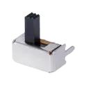
SLW-864574-5A-RA-N-D
Slide Switch SPDT Through Hole, Right Angle The SLW-864574-5A-RA-N-D, manufactured by Same Sky (formerly CUI Devices), is a single-pole double-throw (SPDT) slide switch with a right-angle, through-hole mounting configuration. It features a raised actuator for easy manual operation and is intended for PCB-based applications where space is limited but dependable switching is required. Key Features Switch Type: Slide switch (manual) Circuit Configuration: SPDT (Single Pole Double Throw) Switch Function: ON–ON (selects between two circuits) Contact Timing: Non-shorting (break-before-make) Mounting Type: Through-hole, right-angle Actuator: Raised slide, ~5 mm height Electrical & Mechanical Characteristics Rated Voltage: 50 VDC Rated Current: up to 500 mA Contact Resistance: ≤ 100 mΩ Insulation Resistance: ≥ 100 MΩ Operating Temperature: -20°C to +70°C Mechanical/Electrical Life: ~10,000 cycles Physical Characteristics Dimensions: approx. 8.6 × 4.5 × 6–7 mm Actuator Travel: ~2 mm Termination: PC pins (through-hole soldering) Orientation: Horizontal (right-angle insertion into PCB) #CommonPartsLibrary #Switch
21 Uses0 StarsG6K-2P-Y-DC5
Telecom Relay DPDT (2 Form C) Through Hole The G6K-2P-Y DC5 is a compact, ultra-miniature signal relay designed for high-density PCB mounting applications. Manufactured by Omron, this relay features a DPDT (2 Form C) contact configuration and operates with a 5 VDC coil. It is optimized for switching low-level signals and is commonly used in telecommunications, test and measurement equipment, and consumer electronics where space-saving and high reliability are critical. Key Features Ultra-miniature, low-profile design for high-density mounting DPDT (2 Form C) contact configuration High sensitivity coil (low power consumption) Gold-clad contacts for low-level signal switching High reliability and long mechanical life Fully sealed construction (flux protection) Suitable for surface-mount and through-hole variants (depending on suffix) Electrical Characteristics Coil Specifications Rated Coil Voltage: 5 VDC Coil Resistance: ~125 Ω Coil Current: ~40 mA Power Consumption: ~200 mW Must Operate Voltage: ≤ 75% of rated voltage Must Release Voltage: ≥ 10% of rated voltage Contact Specifications Contact Configuration: DPDT (2 Form C) Contact Material: Gold-clad silver alloy Contact Rating: 1 A at 30 VDC 0.5 A at 125 VAC Maximum Switching Voltage: 125 VAC / 60 VDC Maximum Switching Current: 1 A Maximum Switching Power: 30 W (DC) 62.5 VA (AC) Timing Characteristics Operate Time: ≤ 3 ms Release Time: ≤ 3 ms Insulation Characteristics Insulation Resistance: ≥ 1,000 MΩ (at 500 VDC) Dielectric Strength: Between Coil and Contacts: 1,000 VAC (1 min) Between Open Contacts: 500 VAC (1 min) Mechanical Characteristics Mounting Type: Through-hole (Y variant, PCB terminal) Weight: ~1 g Enclosure: Sealed (flux-resistant) Environmental Specifications Operating Temperature Range: -40°C to +70°C Storage Temperature Range: -40°C to +85°C Vibration Resistance: 10 to 55 Hz, 1.5 mm double amplitude Shock Resistance: 1,000 m/s² Life Expectancy Mechanical Life: ≥ 100 million operations Electrical Life: ≥ 100,000 operations (at rated load) Applications Telecommunications equipment Test and measurement instruments Audio signal routing Industrial control systems Consumer electronics Package Information Manufacturer: Omron Electronics Series: G6K Part Number: G6K-2P-Y DC5 #commonpartslibrary #relay
141 Uses0 StarsPEC06SAAN
Connector Header Through Hole 6 position 0.100" (2.54mm) The PEC06SAAN is a compact, low-cost incremental rotary encoder manufactured by Bourns. It is designed for user interface applications requiring precise rotational input, such as volume controls, menu navigation, and position sensing. This encoder provides reliable quadrature output signals and is suitable for through-hole PCB mounting. Its robust mechanical design ensures long operational life and consistent performance in consumer and industrial electronics. Key Features Incremental (relative) rotary encoder Compact, space-saving design Through-hole mounting configuration Quadrature output (A and B channels) Optional integrated push switch (depending on variant) Detent and non-detent options available High reliability with long rotational life RoHS compliant Electrical Characteristics Supply voltage: Typically 5 VDC (logic-level output) Output type: Digital quadrature (A/B signals) Contact resistance: ≤ 100 mΩ Insulation resistance: ≥ 100 MΩ @ 250 VDC Dielectric strength: 300 VAC for 1 minute Mechanical Characteristics Rotation type: Incremental Number of pulses per revolution (PPR): Typically 6 to 24 (variant dependent) Detent positions: Variant dependent Rotational torque: 10 to 70 gf·cm (typical range) Shaft length: Varies by suffix (e.g., 15 mm typical) Shaft type: Knurled or D-cut (variant dependent) Mounting type: Through-hole PCB Terminal type: PC pins Environmental Specifications Operating temperature range: −30°C to +70°C Storage temperature range: −40°C to +85°C Humidity: Up to 85% RH (non-condensing) Mechanical Life Rotational life: Up to 30,000 cycles (typical) Physical Dimensions Body size: Approximately 12 mm × 11 mm × 5 mm (excluding shaft) Shaft diameter: Typically 6 mm Pin pitch: Standard 2.54 mm Applications Consumer electronics (audio controls, appliances) Industrial control panels Embedded systems and microcontroller interfaces Automotive user interfaces Instrumentation and test equipment #commonpartslibrary #connector #header
28 Uses0 StarsTPS22995RZGR
Power Switch/Driver 1:1 N-Channel 3.8A 6-WQFN-HR (1.5x0.75) The TPS22995RZGR is a high-current, low ON-resistance load switch designed for power distribution and power sequencing applications. It features an integrated N-channel MOSFET capable of handling high load currents while maintaining minimal voltage drop. The device includes controlled rise time to reduce inrush current, making it suitable for sensitive power rails and battery-powered systems. It also integrates thermal shutdown and overcurrent protection, ensuring safe operation under fault conditions. Its compact package and low quiescent current make it ideal for portable and space-constrained designs. Key Features Ultra-low ON-resistance (R<sub>ON</sub>) Wide input voltage range High continuous output current capability Controlled slew rate for inrush current limiting Low quiescent current Thermal shutdown protection Reverse current blocking (when disabled) Active high enable pin (ON pin) Compact WQFN package Electrical Characteristics Input Voltage Range: 0.5 V to 5.5 V ON-Resistance (R<sub>ON</sub>): Typically ~5 mΩ (VIN = 5 V) Continuous Output Current: Up to 6 A (typical, PCB dependent) Quiescent Current: Typically < 10 µA Shutdown Current: Typically < 1 µA Enable Threshold Voltage: ~0.9 V (typical) Functional Description The TPS22995RZGR operates as a load switch that connects or disconnects a power supply to a load using an internal MOSFET controlled by an enable (ON) pin. When the ON pin is asserted high, the device turns on with a controlled rise time, limiting inrush current. When disabled, the switch turns off quickly and prevents reverse current flow from the output to the input. Integrated protection features such as thermal shutdown ensure reliability during abnormal operating conditions. Absolute Maximum Ratings Input Voltage (VIN): -0.3 V to 6 V ON Pin Voltage: -0.3 V to 6 V Output Voltage (VOUT): -0.3 V to VIN + 0.3 V Operating Junction Temperature: -40°C to +125°C Storage Temperature: -65°C to +150°C Package Information Package Type: WQFN (RZG) Package Size: 3 mm × 3 mm Mounting Type: Surface Mount Pin Count: 12 Applications Power rail switching Portable electronics USB power distribution Solid-state drives (SSD) Battery-powered systems Embedded systems power management Advantages Minimizes power loss due to low R<sub>ON</sub> Reduces system inrush current Enhances system reliability with built-in protections Suitable for high-current, compact designs #commonpartslibrary #integratedcircuit #powermanagement
86 Uses0 Stars2SC5171
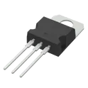
Power Bipolar Transistor, 2A I(C), 180V V(BR)CEO, 1-Element, NPN, Silicon, Plastic/Epoxy, 3 Pin The 2SC5171 is a high-voltage, high-speed NPN bipolar junction transistor designed for switching and amplification applications. It is commonly used in power regulation circuits, switching power supplies, and high-voltage driver stages due to its fast switching characteristics and high collector-emitter voltage capability. The device is typically housed in a TO-220 package, providing good thermal performance for medium to high power applications. Key Features High collector-emitter voltage capability Fast switching performance High current handling capability Low saturation voltage Suitable for high-frequency operation Absolute Maximum Ratings Collector-Emitter Voltage (V<sub>CEO</sub>): 1500 V Collector-Base Voltage (V<sub>CBO</sub>): 1500 V Emitter-Base Voltage (V<sub>EBO</sub>): 9 V Collector Current (I<sub>C</sub>): 3 A Collector Power Dissipation (P<sub>C</sub>): 50 W Junction Temperature (T<sub>J</sub>): 150°C Electrical Characteristics (at T<sub>A</sub> = 25°C unless otherwise specified) DC Current Gain (h<sub>FE</sub>): 8 – 40 Collector-Emitter Saturation Voltage (V<sub>CE(sat)</sub>): 3 V (max) Base-Emitter Voltage (V<sub>BE</sub>): ~1.5 V (typ) Collector Cutoff Current (I<sub>CBO</sub>): 1 mA (max) Transition Frequency (f<sub>T</sub>): 4 MHz (typ) Package Information Package Type: TO-220 Mounting Type: Through-hole Pin Configuration: Pin 1: Base Pin 2: Collector Pin 3: Emitter Applications Switching power supplies High-voltage switching circuits CRT display circuits Motor control circuits General-purpose high-voltage amplification #CommonPartsLibrary #Transistors #Bipolar(BJT) #NPN
1 Uses0 StarsRAA2361052GNP#HC5
Single output buck-boost converter 130nA input quiescent current 96% peak efficiency (VIN = 3.6V; VOUT = 3.3V) Output current: up to 400mA (VIN > 2.5V, VOUT = 3.3V) Input voltage range: 1.8V to 5.5V, supports single-cell Li-ion, 2x or 31.5V AA/AAA batteries Output voltage range: 1.8V to 5.0V Output voltage control using a pin reader (RAA236105) Selectable input current limit DVS with settable slew rate control Selectable forced bypass power saving mode PWM/PFM and buck/bo Input voltage range: 1.8 V to 5.5 V Output voltage range: 1.8 V to 5.0 V (programmable) Output current: up to 400 mA Peak efficiency: up to ~96% Quiescent current (IQ): ~100 nA class (ultra-low power mode) Very low standby consumption (ideal for battery-powered systems) Bypass mode available for near-zero regulation overhead Topology: Synchronous buck-boost converter Can step up or step down voltage automatically Maintains stable output even when input varies above/below output #CommonPartsLibrary #IntegratedCircuit #PowerManagement #Voltage-regulator #Switching-regulator #RAA2361052
116 Uses0 Stars