Interface ICs
An interface IC is a type of integrated circuit that is designed to facilitate communication between two devices or systems. These devices are commonly used in electronic systems to enable the transfer of data and control signals between different components or subsystems. Some common use cases for interface ICs include connecting microcontrollers to peripherals such as sensors or displays, linking multiple processors together in a network, and enabling communication between devices using different communication protocols. Flux.ai has the world's largest community-driven public library of interface ICs, with footprints, symbols, datasheets, and simulation models. This library is a valuable resource for engineers and designers who need access to accurate and up-to-date information on these important components. Whether you are working on a new design project or simply looking to learn more about interface ICs, Flux.ai is an excellent resource to help you find the information you need.
STM32G071K8U6
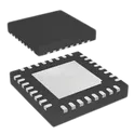
STM32U073 Series – ultra-low-power 32-bit microcontroller based on the Arm Cortex-M0+ core operating up to 56 MHz. Features up to 256 KB Flash memory, 40 KB SRAM, USB Full-Speed interface, integrated LCD controller, advanced analog peripherals, and extremely low power consumption. Designed for battery-powered, portable, industrial, smart metering, IoT, wearable, medical, and consumer electronics applications. Includes ADC, DAC, op-amp, comparators, RTC, DMA, timers, communication interfaces, and multiple low-power operating modes. Search Keywords: STM32U073, STM32U073RBT6, STM32U073CBT6, STM32U073 MCU, STMicroelectronics MCU, Cortex-M0+ Microcontroller, Ultra Low Power MCU, ARM Microcontroller, USB Microcontroller, LCD Controller MCU, Battery Powered MCU, Embedded Controller, IoT Microcontroller, Industrial MCU, Smart Meter MCU, Wearable MCU, 256KB Flash MCU, 40KB SRAM MCU, Low Power Embedded System, STM32U0 Series Hashtags: #STM32U073 #STM32U0 #STM32 #STMicroelectronics #CortexM0Plus #ARMMCU #Microcontroller #UltraLowPower #EmbeddedSystems #USBMCU #LCDController #IoT #WearableElectronics #SmartMeter #IndustrialElectronics #BatteryPowered #FirmwareDevelopment #ElectronicsDesign #PCBDesign #EmbeddedHardwareST Microelectronics STM32G071K8U6 UFQFPN-32_L5.0-W5.0-P0.50-TL-EP3.5 LCSC Part Number: C724237 JLCPCB Part Class: Extended Part Manufactured by ST(意法半导体)
5 Uses0 StarsTPT487L1-DF6R
1/1 Transceiver Half RS485 8-DFN (3x3) 3PEAK TPT487 – half-duplex RS-485/RS-422 transceiver designed for robust industrial communication networks. Operates from a 3.0 V to 5.5 V supply and supports data rates up to 500 kbps. Features true 1/8-unit-load receiver input, allowing up to 256 nodes on a single RS-485 bus. Includes IEC 61000 ESD protection, hot-swap capability, full fail-safe receiver operation, and wide operating temperature range from -40°C to +125°C. Suitable for industrial automation, motor drives, building control systems, and communication infrastructure. Search Keywords: TPT487, 3PEAK TPT487, RS485 Transceiver, RS422 Transceiver, Half Duplex RS485, Industrial Communication IC, 1/8 Unit Load Transceiver, 256 Node RS485, ESD Protected RS485, Fail Safe Receiver, Hot Swap RS485, Differential Bus Transceiver, UART to RS485, Modbus Interface, Industrial Automation Communication, Building Automation, Motor Drive Communication, IEC61000 Protected Transceiver, 500kbps RS485, Wide Temperature Transceiver Hashtags: #TPT487 #3PEAK #RS485 #RS422 #RS485Transceiver #IndustrialCommunication #Modbus #UART #DifferentialBus #FieldBus #IndustrialAutomation #MotorControl #BuildingAutomation #ESDProtection #FailSafeReceiver #HotSwap #EmbeddedSystems #ElectronicsDesign #PCBDesign #CommunicationInterface
10 Uses0 StarsPESD3V3L1BA-N
SOD-323 ESD and Surge Protection (TVS/ESD) ROHS PESD3V3L1BA-N SOD-323_L1.8-W1.3-LS2.5-BI LCSC Part Number: C316020 JLCPCB Part Class: Extended Part Manufactured by BORN(伯恩半导体) PESD3V3 Bidirectional TVS (Transient Voltage Suppressor) diode, 480 W peak pulse power (8/20 µs), silicon avalanche technology, designed for ESD, EFT, and surge protection of sensitive electronic circuits. Low clamping voltage, low leakage current, IEC 61000-4-2 ±30 kV contact/air discharge protection, IEC 61000-4-4 EFT protection, and IEC 61000-4-5 surge protection. Supplied in compact SOD-323 package, suitable for data lines, communication interfaces, microcontroller I/O, USB, RS-485, CAN, industrial control systems, computers, and portable electronics. Search Keywords: TVS Diode, Bidirectional TVS, Transient Voltage Suppressor, ESD Protection Diode, Surge Protection Diode, SOD323 TVS, IEC61000-4-2 Protection, IEC61000-4-4 EFT Protection, IEC61000-4-5 Surge Protection, 480W TVS, Low Capacitance TVS, Signal Line Protection, Data Line Protection, USB Protection Diode, CAN Bus Protection, RS485 Protection, Ethernet Protection, EMC Protection, ESD Suppressor, Silicon Avalanche Diode Hashtags: #TVS #TVSDiode #TransientVoltageSuppressor #ESDProtection #SurgeProtection #EFTProtection #SOD323 #BidirectionalTVS #SignalProtection #DataLineProtection #USBProtection #RS485Protection #CANBusProtection #EMCProtection #IEC6100042 #IEC6100044 #IEC6100045 #CircuitProtection #ElectronicsDesign #IndustrialElectronics
513 Uses0 Stars2472
Adafruit 2472 BNO055 breakout Adafruit BNO055 Absolute Orientation Sensor is a 9-DoF intelligent motion tracking module based on the Bosch BNO055 system-in-package sensor. The device integrates a 3-axis accelerometer, 3-axis gyroscope, 3-axis magnetometer, and an onboard ARM Cortex-M0 microcontroller running Bosch sensor fusion algorithms. Unlike traditional IMUs, the BNO055 directly outputs absolute orientation data in Euler angles, quaternions, linear acceleration, gravity vectors, and calibration information, eliminating the need for complex sensor fusion calculations on the host MCU. The sensor communicates via I²C or UART interfaces and is widely used in robotics, drones, autonomous vehicles, VR/AR systems, motion tracking, navigation, balancing robots, wearable devices, and orientation sensing applications. Search Keywords: BNO055, Adafruit BNO055, Absolute Orientation Sensor, 9DOF Sensor, IMU Sensor, Bosch BNO055, Sensor Fusion IMU, Orientation Sensor, Quaternion Sensor, Euler Angle Sensor, Motion Tracking Sensor, Accelerometer Gyroscope Magnetometer, AHRS Sensor, Robotics IMU, Drone Orientation Sensor, Wearable Motion Sensor, Navigation Sensor, I2C IMU Sensor, UART IMU Sensor, Absolute Position Sensor Hashtags: #BNO055 #Adafruit #BoschSensortec #IMU #9DOF #OrientationSensor #MotionTracking #SensorFusion #Quaternion #AHRS #Accelerometer #Gyroscope #Magnetometer #Robotics #DroneTechnology #EmbeddedSystems #IoTDevices #ElectronicsDesign #PCBDesign #HardwareEngineering
9 Uses0 StarsMCP6004-E/P
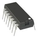
MCP6001/MCP6002/MCP6004 are low-power rail-to-rail input/output operational amplifiers from Microchip Technology designed for battery-powered, portable, industrial, automotive, and general-purpose analog applications. Operating from a single supply voltage of 1.8 V to 6.0 V, the family provides a typical gain-bandwidth product of 1 MHz, low quiescent current of only 100 µA per amplifier, and full rail-to-rail input/output operation for maximum dynamic range. Available in single, dual, and quad amplifier versions, the MCP600x series is well suited for sensor interfaces, photodiode amplifiers, analog filters, signal conditioning, portable instrumentation, IoT devices, battery-powered electronics, and embedded analog circuits requiring low power consumption and cost-effective performance. Search Keywords: MCP6001, MCP6002, MCP6004, Microchip MCP6001, Rail to Rail Op Amp, Low Power Operational Amplifier, Single Supply Op Amp, General Purpose Op Amp, Analog Signal Conditioning, Sensor Amplifier, Photodiode Amplifier, Battery Powered Amplifier, Low Voltage Op Amp, 1MHz Op Amp, Rail to Rail Input Output Amplifier, Portable Electronics Amplifier, Embedded Analog Circuit, Analog Filter Amplifier, Precision Signal Amplifier, Microchip Operational Amplifier Hashtags: #MCP6001 #MCP6002 #MCP6004 #Microchip #OperationalAmplifier #OpAmp #RailToRail #AnalogElectronics #SignalConditioning #SensorInterface #LowPowerDesign #BatteryPowered #EmbeddedSystems #AnalogCircuit #ElectronicsDesign #PCBDesign #HardwareEngineering #IoTDevices #Instrumentation #ElectricalEngineering
2 Uses0 StarsDS90LV049QMTX_NOPB
DS90LV049Q is an automotive-qualified dual LVDS line driver and receiver pair from Texas Instruments designed for high-speed differential data transmission in low-power automotive and industrial communication systems. The device converts LVTTL/LVCMOS logic signals to Low Voltage Differential Signaling (LVDS) and vice versa, supporting data rates exceeding 400 Mbps while maintaining low power dissipation and excellent noise immunity. Featuring AEC-Q100 Grade 1 qualification, integrated fail-safe receiver biasing, TRI-STATE output control, low channel-to-channel skew, and a single 3.3 V supply operation, the DS90LV049Q is optimized for robust high-speed serial communication, sensor interfaces, display systems, industrial automation equipment, and automotive electronic control units requiring reliable differential signaling. DS90LV049QMTX/NOPB DS90LV049Q, Texas Instruments DS90LV049Q, LVDS Driver Receiver, Dual LVDS Transceiver, LVDS Line Driver, LVDS Receiver, Differential Signaling IC, High Speed Communication Interface, 400Mbps LVDS, Automotive LVDS Interface, AEC-Q100 Transceiver, LVTTL to LVDS Converter, LVCMOS to LVDS Converter, Differential Data Transmission, Industrial Communication IC, Display Interface Driver, High Speed Serial Communication, Automotive Communication IC, Low Power LVDS Transceiver, TI Interface IC Hashtags: #DS90LV049Q #TexasInstruments #LVDS #LVDSDriver #LVDSReceiver #DifferentialSignaling #HighSpeedCommunication #AutomotiveElectronics #AECQ100 #SerialCommunication #InterfaceIC #IndustrialElectronics #EmbeddedSystems #HardwareDesign #ElectronicsDesign #PCBDesign #SignalIntegrity #DataTransmission #CommunicationSystems #ElectricalEngineering
2 Uses0 Stars88615-5005
15 Position D-Sub Plug, Male Pins Connector The 88615-5005 is a D-subminiature connector manufactured by 3M, configured as a plug-style connector with male pin contacts. D-subminiature connectors, commonly known as D-Sub connectors, are among the most widely used and longest-standing rectangular connector standards in the electronics industry, recognized by their characteristic trapezoidal metal shell that provides a self-aligning, polarized mating interface and a degree of mechanical shielding for the contacts housed within. This particular connector is built around a defined male pin contact arrangement housed within the standard D-shaped metal shell, which serves to guide correct mating alignment with its corresponding female socket connector counterpart while also helping to reduce the risk of bent or damaged pins during the mating process. As a plug-style device with pin contacts, this connector is typically mounted on a cable assembly, panel, or enclosure and is intended to mate with a female D-Sub receptacle mounted on a printed circuit board, another cable assembly, or an equipment panel, forming a complete signal or low-power interconnect path between two systems or subsystems. D-Sub connectors of this style have long been used across an extremely broad range of applications, including legacy computer peripheral interfaces, industrial control systems, test and measurement equipment, instrumentation racks, and many other applications requiring a rugged, field-serviceable, and widely interoperable multi-pin connection. Their enduring popularity stems from the connector family's mechanical robustness, ease of hand assembly and field termination, broad availability of compatible mating hardware such as backshells and hoods, and long-established presence in legacy and ruggedized electronic system designs across commercial, industrial, and aerospace sectors. 3M's D-Sub connector assemblies in this product family are typically constructed using a metal or metal-plated shell to provide mechanical strength and a degree of electromagnetic shielding, paired with an insulating housing that holds the individual pin contacts in precise alignment. The pin contacts themselves are typically machined or stamped from a conductive alloy and plated to ensure low-resistance, corrosion-resistant electrical contact across the connector's service life. As is typical for connectors in this product class, the device is intended for general-purpose signal and low-power interconnection rather than high-speed digital or high-current power transmission, making it well suited to control signal routing, instrumentation wiring, and other moderate-density interconnect applications. Spec Sheet Identification Part Number: 88615-5005 Connector Family: D-Sub Connector Assemblies Manufacturer: 3M Connector Type / Configuration Type: D-Subminiature connector Gender: Plug, male pin contacts Contact Style: Male pins Shell Style: Standard D-shaped trapezoidal metal shell Mechanical Specifications Mounting Style: Cable-mount or panel-mount plug configuration Mating Interface: Standard D-Sub polarized shell, self-aligning Contact Material: Conductive alloy pin contacts, plated for corrosion resistance and low contact resistance Application Context Typical Use: General-purpose signal and low-power interconnection Common Applications: Industrial control systems, instrumentation, test and measurement equipment, legacy peripheral interfaces, panel and rack wiring Compatibility Mates With: Corresponding D-Sub female socket receptacle connector Accessory Compatibility: Compatible with standard D-Sub backshells, hoods, and jackscrew hardware Environmental & Qualification Construction Class: General-purpose connector construction typical of the D-Sub product family RoHS Compliance: Per 3M product documentation for this series Packaging Supply Format: Standard connector packaging per 3M distribution practices #88615 #3M #DSubConnector #DSubminiature #ConnectorAssembly #MalePinConnector #PlugConnector #SignalConnector #IndustrialConnector #InstrumentationConnector #PanelMount #CableAssembly #RectangularConnector #ElectronicComponents #PCBDesign #HardwareEngineering #EngineeringSpec #ComponentLibrary #CommonPartsLibrary #ConnectorDatasheet
0 Uses0 StarsTCAN1462DRQ1
1/1 Transceiver Half CANbus 8-SOIC The TCAN1462DRQ1 is an automotive-grade, fault-protected CAN FD transceiver manufactured by Texas Instruments, designed to serve as the physical-layer interface between a CAN protocol controller and the physical CAN bus wiring in a vehicle network. The device meets the physical layer requirements of the high-speed CAN standard and additionally complies with the Signal Improvement Capability specification, a more demanding industry standard developed to address signal integrity challenges that arise in complex, high-node-count automotive network topologies. A central feature of this transceiver is its ability to actively reduce signal ringing that occurs during dominant-to-recessive bus transitions, a phenomenon that becomes increasingly problematic as networks grow larger, bus speeds increase, and more unterminated branch connections are introduced into the topology. By suppressing this ringing, the device allows the network to reliably support higher CAN FD data rates and more complex star or multi-drop topologies than would be achievable with a conventional CAN transceiver, enabling designers to extract the full throughput benefit of the CAN FD protocol even in challenging real-world wiring harness configurations. The device also meets tighter bit-timing symmetry requirements than standard CAN FD transceivers, which widens the timing margin available for correctly sampling each bit and helps prevent communication errors caused by ringing and bit distortion in large, complex networks. This particular part number is pin-compatible with other widely used 8-pin CAN FD transceivers, allowing it to serve as a drop-in upgrade path for existing automotive electronic control unit designs seeking improved signal integrity without requiring a board redesign. The device supports a low-power standby mode that allows the transceiver to enter a reduced-current state while still being able to detect a wake-up pattern transmitted over the bus, supporting remote wake-up functionality that is essential for modern vehicle networks where many control modules must remain dormant but responsive while the vehicle is parked. Robust fault protection is built into the device to support reliable operation in the harsh electrical environment of a vehicle, including comprehensive bus fault protection against high-voltage transients and short circuits, along with internal mechanisms to detect undervoltage conditions, prevent device damage from excessive internal temperature, and guard against a stuck or fault-driven transmit input from indefinitely holding the bus in a dominant state. Together, these protection features allow the transceiver to maintain network integrity even when subjected to electrical faults, wiring harness damage, or unexpected operating conditions common in automotive environments. The device is housed in a small-outline surface-mount package suited to space-constrained automotive electronic control unit designs and is qualified to automotive electronics reliability standards, reflecting its suitability for deployment in body, chassis, powertrain, and infotainment network nodes throughout a vehicle. Spec Sheet Identification Part Number: TCAN1462DRQ1 Device Family: TCAN1462-Q1 Manufacturer: Texas Instruments Functional Classification Device Type: CAN FD transceiver Compliance: High-speed CAN physical layer standard, Signal Improvement Capability (SIC) specification Pin Compatibility: Compatible with standard 8-pin CAN FD transceiver pinouts Signal Integrity Features Ringing Suppression: Active reduction of dominant-to-recessive edge ringing Bit Timing: Tightened bit-timing symmetry for improved sampling margin Supported Topologies: Large, complex networks including star topologies with multiple unterminated stubs Data Rate Support: Enhanced throughput at elevated CAN FD data rates Power & Operating Modes Standby Mode: Low-power standby with bus wake-up pattern detection Wake-Up Compliance: Remote wake-up per high-speed CAN wake-up pattern standard Protection Features Bus Fault Protection: High-voltage bus fault protection Undervoltage Detection: Integrated undervoltage monitoring Thermal Shutdown: Integrated overtemperature protection Driver Timeout: Dominant-state timeout protection on transmit input Environmental & Qualification Temperature Grade: Extended automotive operating temperature range Automotive Qualification: AEC-Q100 qualified Lifecycle Status: Active production Package Package Type: Small-outline surface-mount package (SOIC style) Mounting: Surface mount technology (SMT) Terminal Form: Gull-wing leads Packaging Format Supply Format: Tape-and-reel or cut-tape packaging options #TCAN1462 #TexasInstruments #CANTransceiver #CANFD #AutomotiveIC #AECQ100 #SignalImprovementCapability #VehicleNetworking #InVehicleNetwork #FaultProtected #SOIC #SurfaceMount #AutomotiveElectronics #ECU #SemiconductorIC #EngineeringSpec #ComponentLibrary #CommonPartsLibrary #RoHSCompliant #PhysicalLayerIC
32 Uses0 Stars1782
MCP9808 - Temperature Sensor Evaluation Board The Adafruit 1782 MCP9808 Temperature Sensor Breakout is a compact sensor evaluation board that enables high-accuracy digital temperature measurement using the MCP9808 sensor IC. It supports an I²C communication interface, allowing simple connection to microcontrollers while maintaining high precision over a wide operating temperature range. Key Features High Accuracy Temperature Sensing: Typical accuracy of ±0.25°C for reliable temperature monitoring. Wide Temperature Range: Measures temperatures from -40°C to +125°C. Digital I²C Interface: Simple two-wire communication interface for easy integration with embedded systems. High Resolution: Provides temperature resolution up to 0.0625°C. Wide Supply Voltage Range: Operates from 2.7V to 5.5V, compatible with common logic levels. Multiple Device Addressing: Configurable address pins allow multiple sensors to share the same I²C bus. Compact Breakout Board Design: Includes supporting components and headers for quick prototyping. Low Power Consumption: Suitable for battery-powered and portable applications. Applications IoT environmental monitoring Weather stations Industrial temperature monitoring Battery management systems Data logging equipment Embedded control systems Hashtags #Adafruit1782 #MCP9808 #TemperatureSensor #DigitalSensor #I2C #EmbeddedSystems #IoT #Arduino #RaspberryPi #SensorModule #ElectronicsDesign #HardwareDevelopment
1 Uses0 StarsNPM1100-QDAA-R7
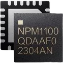
Battery Power Management IC Lithium Ion/Polymer 24-QFN (4x4) nPM1100 is an integrated Power Management IC (PMIC) with a linear-mode lithium-ion/lithium-polymer battery charger in a compact 2.1x2.1 mm WLCSP package. It has a highly efficient, dual-mode configurable output DC/DC buck regulator. nPM1100 is an extremely compact PMIC device, created for space constrained applications with a small lithium-ion or lithium-polymer battery. It is compatible with all nRF52 and nRF53 Series SoCs and supports charging batteries at up to 500 mA through USB, and also delivers up to 150 mA of current to power external components with regulated voltage. A minimum of five passive components are required for operation and the device functions without a control interface. It is the perfect companion for nRF52 and nRF53 multiprotocol SoCs in battery powered designs. Low quiescent current (IQ) extends battery life during shipping and storage with Ship mode, or in operation using auto-controlled hysteretic buck mode for high efficiency down to 1 µA loads. Charge and error indication LED drivers are built in. Charge profile limits are configurable and VBUS current limits can be fixed or auto-controlled with on-chip USB port detection. • 400 mA linear battery charger • Linear charger for lithium-ion/lithium-polymer batteries • Adjustable charge current from 20 mA to 400 mA • Selectable termination voltage of 4.1 V or 4.2 V • Automatic trickle, constant current, and constant voltage charging • Battery thermal protection • Discharge current limitation • JEITA compliant • Li-ion/Li-polymer USB battery charger with a high efficiency buck regulator • 800 nA - Typical quiescent current • 460 nA - Shipping mode quiescent current • Thermal protection • Input regulator • USB compatible current limit of 100 mA and 500 mA • 4.1 V to 6.7 V input voltage range for normal operation • 20 V overvoltage protection • Reverse current protection • 3.0 V to 5.5 V system voltage output • USB port detection supporting the following types: • SDP • CDP/DCP • 1.8 V to 3.0 V, 150 mA step-down buck regulator • Step-down buck regulator with up to 92% efficiency • Automatic transition between hysteretic and pulse width modulation (PWM) modes • Forced PWM mode for clean power operation • Pin-selectable output voltage (1.8 V, 2.1 V, 2.7 V, 3.0 V) • Soft start-up • LED drivers for charger state indication • 5 mA low side LED driver for charging indication • 5 mA low side LED driver for error indication • 2.3 V to 4.35 V battery operating input range • 2.1x2.1 mm WLCSP package • Suitable for two layer PCB design #CommonPartsLibrary #IntegratedCircuit #NordicSemiconductor #nPM1100 #PMIC #BatteryCharger #PowerManagement #LiIon #LiPolymer #BuckConverter #Wearables #IoT #WirelessSensor #LowPowerDesign #USBCharging #EmbeddedSystems #nRF52 #nRF53 #PortableElectronics
23 Uses0 Stars