Connectors
A connector is a device that is used to join two or more electrical or mechanical components. Connectors are an essential part of many electronic and mechanical systems, as they allow for the easy transfer of electricity, data, or other signals between different devices or components. There are many different types of connectors, each designed for specific use cases. Some common use cases for connectors include: * Connecting electronic components in circuit boards * Connecting electrical devices to power sources * Connecting mechanical components in machines and devices * Connecting data cables for networking and communication * Connecting audio and video components in home theater systems Flux.ai has the world's largest community-driven public library of connectors, with footprints, symbols, datasheets, and simulation models. This library is a valuable resource for engineers and designers who need to find and use connectors in their projects.
30340-6002HB
CONN HEADER 40POS DL STR GOLD 3M 303 Series, 2.54mm Pitch 40 Way 2 Row Shrouded Straight PCB Header, Through Hole, Solder Termination 3M 303 Series low-profile board-to-board/socket header connector with 2.54 mm (0.100") pitch, available in straight and right-angle versions. Designed as a low-cost, rugged female header solution for PCB interconnection in embedded systems, development boards, industrial electronics, communication equipment and general-purpose electronic assemblies. Features brass contacts with nickel underplating and gold flash contact finish, glass-filled polyester (PBT) housing rated UL94V-0, orientation marking triangle, end windows for alignment, and compatibility with standard 0.64 mm (0.025") square pin headers. Rated for 1 A current, 500 V insulation withstand voltage, and operation from -55°C to +105°C. Search Keywords: 3M 303 Series, low profile header, female header connector, 2.54mm socket header, 0.100 inch connector, board to board connector, PCB socket connector, right angle header, straight header connector, through hole socket strip, gold flash socket header, 3M header connector, female pin header, electronic connector, embedded system connector Hashtags: #3M #303Series
0 Uses0 Stars2286550-1
2286550-1 is a TE Connectivity Automotive HSD (High-Speed Data) hybrid connector header designed for high-speed data transmission in automotive applications. It is a shielded, right-angle PCB-mounted connector that combines HSD and MQS contacts, making it suitable for Ethernet, LVDS, USB, camera, infotainment, and other vehicle data communication systems. The connector features a 100 Ω controlled impedance design for reliable signal integrity in demanding automotive environments. Key Features Automotive HSD+2MQS hybrid header connector 6-position interface with A-coding Right-angle (horizontal) PCB mounting Board-to-board and wire-to-board connectivity Shielded construction for EMI protection 100 Ω impedance for high-speed data transmission Through-hole solder termination Operating voltage up to 60 VDC Maximum current rating: 2.5 A Operating frequency range: 0 to 3 GHz Gold-plated signal contacts for reliable performance Operating temperature range: -40°C to +105°C Reflow soldering capable Designed for automotive signal applications #CommonPartsLibrary #Connector #TEConnectivity #AutomotiveConnector #HSDConnector #DataConnectivity #HighSpeedData #AutomotiveEthernet #WireToBoard #BoardToBoard #ShieldedConnector #PCBConnector #AutomotiveElectronics #22865501
1 Uses0 StarsD4S20D-40MA5-Z
RF Connectors / Coaxial Connectors Right Angle Plug PCB w/Housing T&R WBlue HSD®, Fakra, Quadraxial Connector Plug, Male Pin 100 Ohms Through Hole, Right Angle Solder D4S20D-40MA5-Z is a right-angle HSD (High-Speed Data) FAKRA quadraxial connector from Rosenberger designed for automotive and industrial high-speed data communication systems. It features a 100 Ω impedance, right-angle PCB mounting, and a secure latch-lock mechanism, making it suitable for infotainment, telematics, camera, and ADAS applications where reliable signal integrity is critical. The connector supports frequencies up to 2 GHz and operates across a wide temperature range of -40°C to +105°C. Key Features: HSD® / FAKRA quadraxial right-angle PCB connector 100 Ω controlled impedance for high-speed data transmission Male plug configuration with latch-lock fastening Through-hole PCB mounting with solder termination Frequency support up to 2 GHz Operating temperature range: -40°C to +105°C Gold-plated center contact for excellent conductivity and corrosion resistance Water-blue Code Z housing for automotive coding identification Robust construction with brass body and nickel finish Ideal for automotive infotainment, ADAS, telematics, and industrial communication systems #D4S20D40MA5Z #Rosenberger #HSDConnector #FAKRA #RFConnector #HighSpeedData #AutomotiveElectronics #ADAS #Telematics #PCBConnector #CoaxialConnector #SignalIntegrity
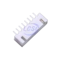
0 Uses0 Stars2.54mm-8P ZZ
CONN HEADER TH 8POS 2.5mm 2.54mm-8P ZZ is a through-hole wire-to-board header connector from the XH-style connector family. It features a single-row 8-position configuration with approximately 2.5 mm pitch spacing, making it suitable for power and signal connections in consumer electronics, industrial controls, LED modules, battery systems, and embedded electronics. The connector is designed for PCB mounting and provides a reliable, low-cost interconnect solution for cable assemblies. Key Features Single-row 8-position (1×8) connector 2.5 mm / 2.54 mm pitch wire-to-board interface Through-hole PCB mounting Compatible with XH-series style housings Rated up to 3 A current Rated up to 250 V Tin-plated brass contacts for reliable conductivity UL94V-0 flame-retardant housing material Operating temperature range: -25°C to +85°C Suitable for power distribution and signal connections in electronic equipment Hashtags #Connector #WireToBoard #XHConnector #2_54mmPitch #ThroughHole #PCBConnector #8PinConnector #ElectronicComponents #Interconnect #EmbeddedSystems #IndustrialElectronics #PowerConnector #SignalConnector #RoHSCompliant
4 Uses0 Stars1726202
8 Position Wire to Board Terminal Block Horizontal with Board 0.200" (5.08mm) Through Hole ## Engineering Specification ## General Description The **1726202** is a Phoenix Contact **MKKDSN series PCB terminal block** designed for compact and reliable wire-to-board connection in printed circuit board assemblies. It is intended for applications that require secure field wiring, serviceable conductor termination, and stable electrical connection between external wiring and PCB circuitry. The component is suitable for industrial control systems, automation equipment, power interfaces, instrumentation, building controls, and general electronic hardware assemblies. ## Device Identification Manufacturer Part Number: **1726202** Manufacturer: **Phoenix Contact** Product Name: **MKKDSN 1,5/ 8-5,08** Product Family: **MKKDSN 1,5** Product Line: **COMBICON Terminals** Device Category: **Connector and Interconnect Component** Device Type: **PCB Terminal Block** Connection Type: **Wire-to-Board Terminal Block** Termination Method: **Screw Connection with Tension Sleeve** Mounting Type: **Through-Hole PCB Mount** ## Functional Description The device functions as a fixed printed circuit board terminal block that allows external conductors to be connected directly to PCB circuits. The screw-clamp connection secures the conductor mechanically while maintaining electrical continuity through the terminal body and solder pins. This makes the component suitable for wiring interfaces that require durability, accessibility, and field-service capability. ## Mechanical Description The terminal block uses a compact green housing with a two-row terminal arrangement and side-access conductor entry. Its layout supports dense wiring connection on a printed circuit board while maintaining practical access for conductor insertion and screw tightening. The through-hole solder pins provide mechanical stability and electrical connection to the host PCB. ## Electrical Description The component is intended for low-voltage power and signal connection applications within the manufacturer’s specified current and voltage ratings. It supports conductor connection for typical industrial and control wiring requirements when used with compatible wire sizes, correct strip length, and proper tightening torque. ## Material and Contact Description The terminal block uses an insulating housing with internal conductive contact elements designed to transfer current from the inserted conductor to the PCB solder connection. The screw connection with tension sleeve helps maintain stable contact pressure and reliable conductor retention during normal operating conditions. ## Mounting and Assembly Description The **1726202** is intended for through-hole PCB soldering, including wave-solder assembly processes. The PCB layout should follow the manufacturer’s recommended hole size, pad pattern, spacing, and soldering guidelines. The component should be positioned to allow safe conductor insertion, screwdriver access, and adequate clearance from nearby parts or enclosure walls. ## Application Suitability The device is suitable for industrial control boards, automation modules, relay boards, power supply interfaces, building automation equipment, instrumentation systems, sensor wiring interfaces, signal distribution boards, and other electronic products requiring secure PCB wire termination. ## Design Considerations The design should account for conductor size compatibility, current carrying requirement, voltage rating, creepage and clearance spacing, tightening torque, solder joint strength, wire routing, and user access during installation or maintenance. The terminal block should not be used beyond the manufacturer’s specified electrical, thermal, or mechanical limits. ## Hashtags #commonpartslibrary #terminalblock #pcbterminalblock #phoenixcontact #mkkdsn #mkkdsnterminalblock #combicon #wiretoboard #screwterminal #fixedterminalblock #throughholecomponent #wavesoldering #soldermount #connector #interconnect #fieldwiring #industrialelectronics #automationequipment #controlsystems #powerinterface #pcbdesign #hardwaredesign #electronicscomponents #electronicparts #engineeringparts #componentlibrary #electronicsengineering
12 Uses0 Stars1726040
2 Position Wire to Board Terminal Block Horizontal with Board 0.200" (5.08mm) Through Hole ## Engineering Specification ## General Description The **1726040** is a Phoenix Contact **MKKDSN series PCB terminal block** designed for wire-to-board electrical connections in printed circuit board assemblies. It is used to provide a secure screw-clamp interface between external wiring and PCB circuitry. The component is suitable for control systems, industrial electronics, power distribution circuits, automation equipment, and general electronic assemblies requiring reliable field wiring termination. ## Device Identification Manufacturer Part Number: **1726040** Manufacturer: **Phoenix Contact** Product Series: **MKKDSN** Device Category: **Connector and Interconnect Component** Device Type: **PCB Terminal Block** Connection Type: **Wire-to-Board Terminal Block** Mounting Type: **Through-Hole PCB Mount** Termination Method: **Screw Connection** ## Functional Description The device functions as a fixed printed circuit board terminal block that allows external conductors to be connected directly to a PCB. The screw-clamp mechanism secures the wire mechanically and electrically, providing a stable connection for signal or power circuits. The terminal block is intended for applications where field wiring must be removable, serviceable, and mechanically secure. ## Mechanical Description The component uses a compact green housing suitable for PCB-mounted assemblies. It is designed for side-entry conductor connection and horizontal board installation. The terminal block construction supports organized wire routing and convenient access for installation, maintenance, and service work. ## Electrical Description The terminal block is intended for low-voltage power and signal applications within the manufacturer’s specified current and voltage ratings. It provides reliable conductor contact when properly installed with compatible wire sizes and appropriate tightening torque. ## Material and Contact Description The connector housing is typically made from insulating material suitable for electrical safety and PCB assembly use. The internal conductive elements provide the electrical path between the inserted wire and the soldered PCB connection. Proper conductor preparation and screw tightening are required to maintain stable electrical performance. ## Mounting and Assembly Description The component is intended for through-hole solder mounting on a printed circuit board. Proper PCB hole sizing, pad layout, soldering process control, and mechanical clearance should be followed according to the manufacturer’s recommended design and assembly guidance. The terminal block should be mounted in a position that allows safe wire insertion and screw access. ## Application Suitability The **1726040** is suitable for industrial control boards, automation equipment, interface modules, power supply circuits, instrumentation, building control systems, relay boards, sensor wiring interfaces, and other electronic products requiring secure PCB wire termination. ## Design Considerations The design should account for wire gauge compatibility, current rating, voltage rating, tightening torque, creepage and clearance requirements, solder joint strength, and accessibility for field wiring. The terminal block should not be used beyond the manufacturer’s specified electrical, thermal, and mechanical limits. ## Hashtags #commonpartslibrary #terminalblock #pcbterminalblock #phoenixcontact #mkkdsn #wiretoboard #connector #interconnect #fixedterminalblock #screwterminal #throughholecomponent #pcbmount #industrialelectronics #automationequipment #controlsystems #powerdistribution #fieldwiring #electronicscomponents #electronicparts #hardwaredesign #pcbdesign #engineeringparts #componentlibrary #electronicsengineering
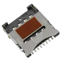
77 Uses0 Stars693022010811
8 Position Card Connector Micro SIM Surface Mount, Right Angle Gold ## Engineering Specification ## General Description The **693022010811** is a Würth Elektronik **WR-CRD Micro SIM card connector** designed for compact electronic devices requiring secure SIM card retention and reliable board-level electrical connection. It is intended for surface-mount printed circuit board assembly and is suitable for communication modules, wireless devices, embedded systems, IoT hardware, and networking equipment. The connector uses a hinged lid mechanism to hold the Micro SIM card in place during operation. ## Device Identification Manufacturer Part Number: **693022010811** Manufacturer: **Würth Elektronik** Product Series: **WR-CRD** Device Category: **Connector and Interconnect Component** Device Type: **Micro SIM Card Connector** Connector Style: **Hinge Type** Mounting Type: **Surface Mount, Right Angle** ## Functional Description The device functions as a board-mounted Micro SIM card interface. It provides mechanical retention and electrical contact between the SIM card and the host printed circuit board. The hinged lid design allows the SIM card to be placed into the connector and secured during operation, helping maintain contact stability in compact electronic assemblies. ## Mechanical Description The connector is designed with a low-profile surface-mount construction suitable for space-constrained PCB layouts. It uses a hinged card-retention mechanism and is intended for horizontal or right-angle card installation. The mechanical structure supports reliable insertion, retention, and removal of the Micro SIM card during normal use. ## Electrical Description The connector is intended for signal-level SIM card interface applications. It provides multiple gold-plated contact positions for stable electrical connection between the SIM card and the host circuit. The device should be used within the manufacturer’s specified voltage, current, contact resistance, and insulation limits. ## Material and Contact Description The connector uses copper alloy contacts with gold plating for reliable signal transfer and corrosion resistance. The housing and mechanical retention structure are designed for surface-mount assembly and repeated card handling within the rated operating conditions. ## Mounting and Assembly Description The component is suitable for automated surface-mount PCB assembly. Proper land pattern design, soldering profile control, and mechanical clearance should be followed according to the manufacturer’s recommended layout and assembly guidance. The PCB design should provide stable grounding, correct pad alignment, and adequate clearance for SIM card insertion and lid operation. ## Application Suitability The **693022010811** is suitable for cellular communication devices, IoT modules, wireless routers, embedded modems, tracking systems, smart meters, industrial communication equipment, portable electronics, and other products requiring a Micro SIM card interface. ## Design Considerations The connector should be placed in an accessible area of the PCB to allow SIM card installation and removal. Designers should avoid excessive mechanical stress on the hinged lid, improper solder joint loading, contamination of the contact area, and operation beyond the specified environmental and electrical ratings. ## Hashtags #commonpartslibrary #connector #simconnector #microsimconnector #wurthelektronik #wrcrd #cardconnector #memoryconnector #interconnect #pcbconnector #surfacemount #rightangleconnector #smtcomponent #goldplatedcontacts #embeddedhardware #iotdevices #wirelessmodules #communicationdevices #networkingequipment #pcbdesign #hardwaredesign #electronicscomponents #electronicparts #componentlibrary #engineeringparts #electronicsengineering
2 Uses0 Stars