Switches
A switch is a device that allows electricity to flow through a circuit by completing or interrupting the connection. It is a common component in electrical and electronic systems and is used in a variety of applications, such as controlling the flow of electricity in a circuit, turning devices on and off, and routing electrical signals. One of the primary use cases for switches is to control the flow of electricity in a circuit. This can be done by manually flipping the switch or by using a control mechanism, such as a timer or a sensor. Another common use for switches is to turn devices on and off. This can be done using a switch that is built into the device or by using a separate switch that is connected to the device. In addition to these basic use cases, switches can also be used to route electrical signals. For example, a switch can be used to route a signal from one device to another or to direct a signal to a specific circuit or component. If you're looking for a wide variety of switches for your projects, flux.ai has the world's largest community-driven public library of them. The library includes footprints, symbols, datasheets, and simulation models for a wide range of switches, making it easy to find the right switch for your needs.
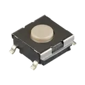
B3FS-1002P
Tactile Switch SPST-NO Top Actuated Surface Mount The B3FS-1002P is a compact, surface-mount tactile switch designed for low-profile input applications. It provides a momentary contact mechanism with a distinct tactile feedback, making it suitable for user interface controls in consumer electronics, industrial devices, and compact embedded systems. The switch features a sealed construction for improved reliability and is optimized for automated PCB assembly processes. Mechanical Characteristics Mounting Type: Surface Mount (SMD) Actuator Style: Top push Actuator Height: Low profile Outline: Rectangular compact body Terminal Type: Gull-wing terminals Sealing: Dust-resistant (sealed construction) Electrical Characteristics Switch Type: Single Pole Single Throw (SPST) Contact Configuration: Normally Open (NO) Rated Voltage: Low voltage DC applications Rated Current: Suitable for signal-level switching Contact Resistance: Low initial contact resistance Insulation Resistance: High insulation resistance between terminals Operating Characteristics Operating Force: Standard tactile force (manufacturer-defined variant) Travel Distance: Short stroke tactile action Operating Life: High durability for repeated actuation cycles Bounce Time: Minimal contact bounce for reliable switching Environmental Characteristics Operating Temperature Range: Wide operating range suitable for consumer and industrial use Storage Temperature Range: Standard electronic component storage conditions Humidity Resistance: Designed to withstand typical ambient humidity conditions Material & Construction Actuator Material: High-strength polymer Housing Material: Heat-resistant plastic Contact Material: Metal alloy with surface plating for durability Terminal Finish: Solderable finish compatible with reflow soldering Packaging Information Packaging Type: Tape and reel Assembly Compatibility: Fully compatible with automated pick-and-place and reflow processes Applications Consumer electronics (keypads, remote controls) Industrial control panels Portable devices Embedded system user interfaces Wearable and compact electronics #commonpartslibrary #switch #tactile
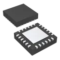
1.3k Uses0 StarsSTUSB4500QTR
USB Controller USB 2.0 I2C Interface 24-QFN (4x4) The STUSB4500QTR is a standalone USB Type-C Power Delivery (PD) controller from STMicroelectronics designed for power sink applications (devices that receive power, like chargers, IoT devices, or battery-powered systems). It enables automatic negotiation of USB Power Delivery contracts (up to 100 W: 20 V / 5 A) without requiring an external microcontroller, thanks to its built-in auto-run algorithm. Power profiles (PDOs) can be pre-configured and stored in internal non-volatile memory, simplifying system design and reducing component count. The device is optimized for modern USB-C designs, offering robust protection, high-voltage tolerance, and support for operation even from a dead battery state. Key Features Power Delivery & Control Standalone USB Type-C™ and USB PD sink controller Supports up to 100 W (20 V, 5 A) power negotiation Auto-run mode (no MCU required) for PD negotiation Up to 3 configurable sink PDO profiles stored in NVM Power Management Dead battery mode support (can start with no battery power) Dual power supply inputs: V<sub>SYS</sub>: 3.0 V – 5.5 V V<sub>DD</sub>: 4.1 V – 22 V Integrated VBUS monitoring and control Integrated Functions Built-in VBUS switch gate drivers (PMOS) Internal/external VBUS discharge paths I²C interface for configuration and monitoring Protection & Reliability Short-to-VBUS protection on CC pins (up to 22 V) High-voltage tolerance: Up to 28 V on VBUS pins ESD protection: 3 kV HBM / 1.5 kV CDM Physical & Environmental Package: QFN-24 (4×4 mm) Operating temperature: –40°C to +105°C Industrial-grade reliability Compliance & Compatibility Certified for: USB Type-C Rev 1.2 USB PD Rev 2.0 Interoperable with USB PD 3.0 #commonpartslibrary #integratedcircuit #usbcontroller
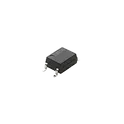
512 Uses0 StarsG3VM-61VY3(TR05)
Solid State Photo-Coupled Relay (Photorelay) SPST-NO (1 Form A) 4-SOP (0.179", 4.55mm) The G3VM-61VY3(TR05) is a single-pole, single-throw normally open (SPST-NO) solid-state relay that uses an LED input and MOSFET output to switch AC or DC loads without mechanical contacts. It provides fast, silent, and highly reliable switching in a very small surface-mount package. Key Characteristics Relay Type: Solid State Relay (Photorelay) Contact Form: SPST-NO (1 Form A) Output Type: MOSFET Load Voltage: Up to 60 V AC/DC Load Current: Up to 700 mA On-Resistance: ~2 Ω max Input Control: LED-driven (low current DC input) Isolation Voltage: ~3.75 kV (input to output) Package: SOP-4 surface-mount (compact form factor) Packaging Option: TR = Tape & Reel for automated assembly How It Works The input LED is energized with a small DC current. It activates an internal photo-coupler. This drives a pair of MOSFETs, turning the load ON or OFF. No mechanical movement → no arcing or contact wear. Key Advantages Silent operation (no clicking sound) Very long life (no mechanical parts) Fast switching speed Compact size for dense PCB layouts Low leakage and stable performance Typical Applications Semiconductor test equipment Industrial control systems Battery-powered devices Data acquisition systems Communication and measurement circuits General-purpose signal switching #CommonPartsLibrary #Relay #SSR #G3VM
117 Uses0 StarsPEC06SAAN
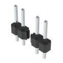
Connector Header Through Hole 6 position 0.100" (2.54mm) The PEC06SAAN is a compact, low-cost incremental rotary encoder manufactured by Bourns. It is designed for user interface applications requiring precise rotational input, such as volume controls, menu navigation, and position sensing. This encoder provides reliable quadrature output signals and is suitable for through-hole PCB mounting. Its robust mechanical design ensures long operational life and consistent performance in consumer and industrial electronics. Key Features Incremental (relative) rotary encoder Compact, space-saving design Through-hole mounting configuration Quadrature output (A and B channels) Optional integrated push switch (depending on variant) Detent and non-detent options available High reliability with long rotational life RoHS compliant Electrical Characteristics Supply voltage: Typically 5 VDC (logic-level output) Output type: Digital quadrature (A/B signals) Contact resistance: ≤ 100 mΩ Insulation resistance: ≥ 100 MΩ @ 250 VDC Dielectric strength: 300 VAC for 1 minute Mechanical Characteristics Rotation type: Incremental Number of pulses per revolution (PPR): Typically 6 to 24 (variant dependent) Detent positions: Variant dependent Rotational torque: 10 to 70 gf·cm (typical range) Shaft length: Varies by suffix (e.g., 15 mm typical) Shaft type: Knurled or D-cut (variant dependent) Mounting type: Through-hole PCB Terminal type: PC pins Environmental Specifications Operating temperature range: −30°C to +70°C Storage temperature range: −40°C to +85°C Humidity: Up to 85% RH (non-condensing) Mechanical Life Rotational life: Up to 30,000 cycles (typical) Physical Dimensions Body size: Approximately 12 mm × 11 mm × 5 mm (excluding shaft) Shaft diameter: Typically 6 mm Pin pitch: Standard 2.54 mm Applications Consumer electronics (audio controls, appliances) Industrial control panels Embedded systems and microcontroller interfaces Automotive user interfaces Instrumentation and test equipment #commonpartslibrary #connector #header
24 Uses0 StarsTPS22995RZGR
Power Switch/Driver 1:1 N-Channel 3.8A 6-WQFN-HR (1.5x0.75) The TPS22995RZGR is a high-current, low ON-resistance load switch designed for power distribution and power sequencing applications. It features an integrated N-channel MOSFET capable of handling high load currents while maintaining minimal voltage drop. The device includes controlled rise time to reduce inrush current, making it suitable for sensitive power rails and battery-powered systems. It also integrates thermal shutdown and overcurrent protection, ensuring safe operation under fault conditions. Its compact package and low quiescent current make it ideal for portable and space-constrained designs. Key Features Ultra-low ON-resistance (R<sub>ON</sub>) Wide input voltage range High continuous output current capability Controlled slew rate for inrush current limiting Low quiescent current Thermal shutdown protection Reverse current blocking (when disabled) Active high enable pin (ON pin) Compact WQFN package Electrical Characteristics Input Voltage Range: 0.5 V to 5.5 V ON-Resistance (R<sub>ON</sub>): Typically ~5 mΩ (VIN = 5 V) Continuous Output Current: Up to 6 A (typical, PCB dependent) Quiescent Current: Typically < 10 µA Shutdown Current: Typically < 1 µA Enable Threshold Voltage: ~0.9 V (typical) Functional Description The TPS22995RZGR operates as a load switch that connects or disconnects a power supply to a load using an internal MOSFET controlled by an enable (ON) pin. When the ON pin is asserted high, the device turns on with a controlled rise time, limiting inrush current. When disabled, the switch turns off quickly and prevents reverse current flow from the output to the input. Integrated protection features such as thermal shutdown ensure reliability during abnormal operating conditions. Absolute Maximum Ratings Input Voltage (VIN): -0.3 V to 6 V ON Pin Voltage: -0.3 V to 6 V Output Voltage (VOUT): -0.3 V to VIN + 0.3 V Operating Junction Temperature: -40°C to +125°C Storage Temperature: -65°C to +150°C Package Information Package Type: WQFN (RZG) Package Size: 3 mm × 3 mm Mounting Type: Surface Mount Pin Count: 12 Applications Power rail switching Portable electronics USB power distribution Solid-state drives (SSD) Battery-powered systems Embedded systems power management Advantages Minimizes power loss due to low R<sub>ON</sub> Reduces system inrush current Enhances system reliability with built-in protections Suitable for high-current, compact designs #commonpartslibrary #integratedcircuit #powermanagement
82 Uses0 StarsUCS7604
UCS 76 04 Is the intelligent bad point continuous transmission series 4 channel65536, level gray scale function LED drive control special circuit, internal integratedMCU, digital interface, data latch, LED high voltage drive and other circuits. Throughthe peripheral MCU control, the separate brightness and cascade control of the chip canrealize the color dot matrix luminescence control of the outdoor large screen. Intelligent bad point continued transmission series IC adopted, advanced HPD intelligent error signal identification technology, the channel error signal identification rate reached more than 99%, and also used the patented dual decodingengine, at the same time monitoring two channels, any channel signal problem real-timeswitch. UCS 7604 RGBW channel output adopts 65535 level gray scale output, with independent current adjustment function of each channel, high precision constant currentdesign, 16K port refresh frequency, so that the picture effect more restore the real color,rich and gorgeous. Excellent product performance, stable and reliable. Double channel bad point transmission function, fault point signal can continue tobe passed down, the overall failure transmission rate of more than 99% Advanced HPD intelligent error signal identification technology, the channel faultidentification rate of more than 99% The patented dual decoding engine simultaneously monitors and decodes two channels,and any problem in the used channel will be switched to normal in real time Channel, and because it is a real-time switch, it is difficult for the human eyeto find the abnormal picture process Can work normally at any frame frequency Advanced channel fault test function, real-time dynamic light on indicates singlechannel fault and channel short circuit recessive fault in the postpartum test oflamps Grayscale level 65536,8 bit (built-in gamma 2.2, corrected to 16 bit) / 12 / 14 / 16 bitdata optional Port refresh frequency is 16K ± 5% high constant current accuracy design RGBW current per channel can be set independently The applied resistance to set the output current, 0-60 mA Data transmission frequencies of 800K / S and 1.6M / S are optional The 1 / 2 / 3 / 4 field mode is optional Chip VDD built-in 5V voltage regulator, output port pressure maximum 30V RGBW channel off, black S-AI anti-interference patented technology, which can greatly reduce and filter outradiation interference and conduction interference S-Drive drive technology and enhanced receiving technology, greatly enhance theconnection distance between points Industrial-grade design, stable and reliable #CommonPartsLibrary #IntegratedCircuit #LED-Driver #4-channel-output
2 Uses0 Stars