Interface ICs
An interface IC is a type of integrated circuit that is designed to facilitate communication between two devices or systems. These devices are commonly used in electronic systems to enable the transfer of data and control signals between different components or subsystems. Some common use cases for interface ICs include connecting microcontrollers to peripherals such as sensors or displays, linking multiple processors together in a network, and enabling communication between devices using different communication protocols. Flux.ai has the world's largest community-driven public library of interface ICs, with footprints, symbols, datasheets, and simulation models. This library is a valuable resource for engineers and designers who need access to accurate and up-to-date information on these important components. Whether you are working on a new design project or simply looking to learn more about interface ICs, Flux.ai is an excellent resource to help you find the information you need.
1726040
2 Position Wire to Board Terminal Block Horizontal with Board 0.200" (5.08mm) Through Hole ## Engineering Specification ## General Description The **1726040** is a Phoenix Contact **MKKDSN series PCB terminal block** designed for wire-to-board electrical connections in printed circuit board assemblies. It is used to provide a secure screw-clamp interface between external wiring and PCB circuitry. The component is suitable for control systems, industrial electronics, power distribution circuits, automation equipment, and general electronic assemblies requiring reliable field wiring termination. ## Device Identification Manufacturer Part Number: **1726040** Manufacturer: **Phoenix Contact** Product Series: **MKKDSN** Device Category: **Connector and Interconnect Component** Device Type: **PCB Terminal Block** Connection Type: **Wire-to-Board Terminal Block** Mounting Type: **Through-Hole PCB Mount** Termination Method: **Screw Connection** ## Functional Description The device functions as a fixed printed circuit board terminal block that allows external conductors to be connected directly to a PCB. The screw-clamp mechanism secures the wire mechanically and electrically, providing a stable connection for signal or power circuits. The terminal block is intended for applications where field wiring must be removable, serviceable, and mechanically secure. ## Mechanical Description The component uses a compact green housing suitable for PCB-mounted assemblies. It is designed for side-entry conductor connection and horizontal board installation. The terminal block construction supports organized wire routing and convenient access for installation, maintenance, and service work. ## Electrical Description The terminal block is intended for low-voltage power and signal applications within the manufacturer’s specified current and voltage ratings. It provides reliable conductor contact when properly installed with compatible wire sizes and appropriate tightening torque. ## Material and Contact Description The connector housing is typically made from insulating material suitable for electrical safety and PCB assembly use. The internal conductive elements provide the electrical path between the inserted wire and the soldered PCB connection. Proper conductor preparation and screw tightening are required to maintain stable electrical performance. ## Mounting and Assembly Description The component is intended for through-hole solder mounting on a printed circuit board. Proper PCB hole sizing, pad layout, soldering process control, and mechanical clearance should be followed according to the manufacturer’s recommended design and assembly guidance. The terminal block should be mounted in a position that allows safe wire insertion and screw access. ## Application Suitability The **1726040** is suitable for industrial control boards, automation equipment, interface modules, power supply circuits, instrumentation, building control systems, relay boards, sensor wiring interfaces, and other electronic products requiring secure PCB wire termination. ## Design Considerations The design should account for wire gauge compatibility, current rating, voltage rating, tightening torque, creepage and clearance requirements, solder joint strength, and accessibility for field wiring. The terminal block should not be used beyond the manufacturer’s specified electrical, thermal, and mechanical limits. ## Hashtags #commonpartslibrary #terminalblock #pcbterminalblock #phoenixcontact #mkkdsn #wiretoboard #connector #interconnect #fixedterminalblock #screwterminal #throughholecomponent #pcbmount #industrialelectronics #automationequipment #controlsystems #powerdistribution #fieldwiring #electronicscomponents #electronicparts #hardwaredesign #pcbdesign #engineeringparts #componentlibrary #electronicsengineering
76 Uses0 Stars1085
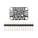
ADS1115 series 16 Bit 860 Samples per Second Analog to Digital Converter (ADC) Evaluation Board Adafruit 1085 ADS1115 Adafruit 4-Channel ADC Breakout based on Texas Instruments ADS1115 (16-bit) or ADS1015 (12-bit) analog-to-digital converter, featuring I2C communication, four single-ended inputs or two differential inputs, programmable gain amplifier (PGA) up to x16, internal voltage reference, programmable comparator, and selectable I2C addresses (0x48–0x4B). Operates from 2.0V to 5.5V and supports interfacing analog sensors with 3.3V and 5V microcontrollers such as Arduino, ESP32, STM32, RP2040, and Raspberry Pi. Search Keywords: Adafruit 4-Channel ADC Breakout, ADS1115 Breakout, ADS1015 Breakout, Adafruit ADS1115, Adafruit ADS1015, I2C ADC Module, 16-bit ADC, 12-bit ADC, 4-channel ADC, differential ADC, programmable gain amplifier, PGA ADC, analog sensor interface, TI ADS1115, TI ADS1015, Raspberry Pi ADC, Arduino ADC module, ESP32 ADC expansion Hashtags: #Adafruit #ADS1115 #ADS1015 #ADCModule #I2CADC #16BitADC #12BitADC #AnalogToDigitalConverter #SensorInterface #DifferentialADC #PGA #Arduino #ESP32 #STM32 #RP2040 #RaspberryPi #DataAcquisition #EmbeddedSystems #AdafruitBreakout
15 Uses0 StarsMAX2871ETJ+
Maxim Integrated PLL Frequency Synthesizer Single 23.5MHz to 6000MHz 32-Pin TQFN EP QFN-32 Maxim None MAX2871ETJ+ Unavailable Maxim Integrated MAX2871 ultra-wideband fractional-N / integer-N PLL frequency synthesizer with integrated VCOs, capable of generating RF frequencies from 23.5MHz to 6.0GHz. Features programmable output dividers (1/2/4/8/16/32/64/128), dual differential RF outputs with programmable output power from -1dBm to +8dBm, low phase noise performance, phase frequency detector up to 140MHz, reference frequency up to 210MHz, fast lock and cycle-slip reduction, automatic/manual VCO selection, on-chip temperature sensor with 7-bit ADC, 4-wire SPI-compatible serial interface, and operation from -40°C to +85°C. Suitable for wireless infrastructure, clock generation, microwave radios, RF signal generation, and test & measurement equipment. MAX2871 Search Keywords: MAX2871, Maxim MAX2871, Analog Devices MAX2871, PLL synthesizer, RF synthesizer, fractional N synthesizer, integer N synthesizer, 6GHz frequency synthesizer, RF signal generator IC, integrated VCO synthesizer, microwave synthesizer, SPI frequency synthesizer, dual output PLL, clock generation IC, wireless infrastructure synthesizer Hashtags: #MAX2871 #MaximIntegrated #AnalogDevices #PLLSynthesizer #FrequencySynthesizer #RFSynthesizer #FractionalNPLL #IntegerNPLL #IntegratedVCO #RFSignalGenerator #MicrowaveRadio #ClockGeneration #WirelessInfrastructure #SPIInterface #TestAndMeasurement #RFDesign #RFIC #PhaseLockedLoop
0 Uses0 Stars