Interface ICs
An interface IC is a type of integrated circuit that is designed to facilitate communication between two devices or systems. These devices are commonly used in electronic systems to enable the transfer of data and control signals between different components or subsystems. Some common use cases for interface ICs include connecting microcontrollers to peripherals such as sensors or displays, linking multiple processors together in a network, and enabling communication between devices using different communication protocols. Flux.ai has the world's largest community-driven public library of interface ICs, with footprints, symbols, datasheets, and simulation models. This library is a valuable resource for engineers and designers who need access to accurate and up-to-date information on these important components. Whether you are working on a new design project or simply looking to learn more about interface ICs, Flux.ai is an excellent resource to help you find the information you need.
TAA3020IRTER
Audio 16 b, 20 b, 24 b, 32 b 768k I2C, I2S, TDM 20-WQFN (3x3) The TAA3020IRTER is a high-performance 2-channel audio analog-to-digital converter (ADC) from Texas Instruments, designed for professional and embedded audio applications. It supports up to two analog microphone/line inputs or four digital PDM microphone channels with simultaneous sampling. The device delivers excellent audio quality with a 104 dB dynamic range, supports sample rates up to 768 kHz, and integrates advanced audio processing features such as programmable gain, digital filters, automatic gain control (AGC), voice activity detection (VAD), and an integrated PLL. It communicates through an I²C control interface and supports I²S, TDM, and Left-Justified (LJ) digital audio formats, making it ideal for smart speakers, conferencing systems, IP cameras, and other high-performance audio acquisition systems. Key Features High-performance 2-channel audio ADC Supports 2 analog microphone/line inputs or 4 digital PDM microphone inputs 104 dB dynamic range (DR) and –95 dB THD+N Sampling rates from 8 kHz to 768 kHz Programmable microphone gain from 0 dB to 42 dB Digital volume control from –100 dB to +27 dB Integrated programmable HPF, biquad filters, and low-latency filter modes Built-in Automatic Gain Control (AGC) and Voice Activity Detection (VAD) Integrated audio PLL and programmable microphone bias supply Supports I²S, TDM, and Left-Justified (LJ) audio interfaces Configurable for 1.8 V or 3.3 V supply operation Available in a compact 20-pin WQFN (RTE) package Operating temperature range: –40°C to +105°C #AudioADC #TexasInstruments #TAA3020 #HighPerformanceADC #I2S #TDM #PDMMicrophone #AudioProcessing #AGC #VAD #EmbeddedAudio #ProfessionalAudio
0 Uses0 StarsDRV8262QDDWRQ1
Bipolar Motor Driver NMOS On/Off, PWM 44-HTSSOP The DRV8262QDDWRQ1 is an automotive-qualified, high-power H-bridge motor driver from Texas Instruments designed for 24 V and 48 V automotive systems. It integrates two H-bridges capable of driving one or two brushed DC motors, a bipolar stepper motor, or thermoelectric coolers (TECs). The device features integrated high-side current sensing, programmable current regulation, and comprehensive protection functions, eliminating the need for external current-sense resistors while reducing PCB area and system cost. It supports wide supply voltages from 4.5 V to 60 V, making it suitable for demanding automotive body electronics and industrial motor control applications. Key Features Automotive AEC-Q100 Grade 1 qualified (-40°C to +125°C) Wide 4.5 V to 60 V operating supply voltage Dual H-bridge or single high-current H-bridge operation Drives: One or two brushed DC motors One bipolar stepper motor One or two thermoelectric coolers (TECs) Up to 8 A peak (dual H-bridge mode) Up to 16 A peak (single H-bridge mode) Low MOSFET on-resistance: 100 mΩ (dual H-bridge) 50 mΩ (single H-bridge) Integrated high-side current sensing with ±4% accuracy Programmable current regulation and current limiting Supports 1.8 V, 3.3 V, and 5 V logic interfaces Configurable PWM control modes (PH/EN or IN/IN) Ultra-low 3 µA sleep current Integrated protection features: Undervoltage Lockout (UVLO) Charge Pump Undervoltage (CPUV) Overcurrent Protection (OCP) Thermal Shutdown (OTSD) Fault output (nFAULT) Functional safety-capable with supporting documentation for automotive system design. #DRV8262QDDWRQ1 #MotorDriver #HBridge #AutomotiveElectronics #BrushedDCMotor #StepperMotor #CurrentSense #AECQ100 #TexasInstruments #EmbeddedSystems #PowerManagement #PCBDesign
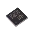
40 Uses0 StarsCH9102X
The CH9102X is a high-speed USB-to-UART bridge IC developed by WCH (Jiangsu Qinheng Microelectronics). It enables seamless communication between a USB host and UART-based embedded systems, making it ideal for programming, debugging, firmware updates, and serial data communication. The device integrates a USB 2.0 Full-Speed interface, an internal clock, power-on reset, and firmware, eliminating the need for an external crystal oscillator. The CH9102X variant supports 3.3 V UART I/O and is widely used on development boards such as ESP32 and other MCU-based designs. Key Features USB 2.0 Full-Speed (12 Mbps) compliant device interface USB-to-UART bridge supporting baud rates from 50 bps to 4 Mbps 3.3 V UART I/O (CH9102X variant) Integrated clock oscillator (no external crystal required) Built-in power-on reset circuit Hardware full-duplex UART with independent TX/RX buffers Supports 5, 6, 7, or 8 data bits Supports None, Odd, Even, Mark, and Space parity Supports RTS/CTS hardware flow control Supports MODEM signals: RTS, CTS, DTR, DSR, DCD, and RI TNOW output for automatic RS-485 transmit/receive control Compatible with built-in CDC drivers and vendor VCP drivers on major operating systems Available in compact RoHS-compliant QFN packages #CH9102X #USBtoUART #USBBridge #UART #SerialConverter #WCH #USB20 #EmbeddedSystems #ESP32 #MCU #RS485 #FirmwareUpdate #Debugging #IoT #PCBDesign
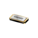
16 Uses0 StarsXTL721-S999-301
32.768 kHz ±20ppm Crystal 9pF 70 kOhms 2-SMD, No Lead The XTL721-S999-301 specification defines the engineering requirements for a crystal oscillator component intended to provide a stable and accurate timing reference for electronic systems. This specification establishes the functional, electrical, mechanical, environmental, and quality requirements necessary to ensure precise frequency generation, reliable operation, and long-term stability in embedded, industrial, communication, and consumer electronic applications. The component is intended for use in applications requiring accurate clock generation and synchronization, including microcontroller-based systems, communication interfaces, digital signal processing, and timing circuits. It provides a highly stable frequency reference with low phase noise and excellent frequency stability to support reliable system operation under varying environmental conditions. Engineering Requirements The crystal component shall be manufactured using high-purity quartz material and precision fabrication processes to ensure consistent resonant frequency characteristics, low aging effects, and dependable long-term performance. The construction shall provide stable oscillation characteristics throughout the specified operating temperature and environmental conditions. Electrical characteristics shall ensure accurate frequency stability, low equivalent series resistance, and reliable oscillation startup when used with compatible oscillator circuits. The component shall maintain stable timing performance under normal supply variations, temperature fluctuations, and continuous operating conditions. Mechanical construction shall be suitable for automated surface-mount assembly and compatible with standard solder reflow manufacturing processes. The package shall provide mechanical robustness and resistance to vibration, mechanical shock, thermal cycling, and handling without degradation of electrical performance or structural integrity. Workmanship shall be free from defects including contamination, package cracking, seal failure, lead deformation, or structural inconsistencies that could adversely affect frequency accuracy or operational reliability. Inspection, validation, and testing shall be performed using calibrated equipment and controlled quality procedures to verify compliance with engineering and manufacturing requirements. Any deviation from this specification shall require formal engineering evaluation, documented technical justification, and approval through the established engineering change control process before implementation. Documentation Supporting documentation shall include engineering drawings, frequency performance specifications, electrical characterization reports, qualification records, inspection reports, reliability data, material declarations, and revision-controlled manufacturing documentation. All documentation shall be maintained under formal configuration management and quality assurance systems to ensure complete product traceability. Revision Control Any modification to this specification shall be managed through the formal engineering change management process. All revisions shall undergo technical review, validation, and approval before release to ensure continued compliance with design intent and applicable engineering standards. #EngineeringSpecification #CrystalOscillator #QuartzCrystal #TimingDevice #ClockGenerator #EmbeddedSystems #IndustrialElectronics #FrequencyControl #QualityAssurance #EngineeringDocumentation
0 Uses0 Stars