Top User Components
Discover the most popular and effective components used in cutting-edge PCB designs on Flux.ai. This collection showcases the components that have been integral to the success of our community's most innovative printed circuit board designs. Ranging from simple resistors to complex integrated circuits, these components represent the best in terms of functionality, reliability, and performance. It’s a treasure trove for anyone looking to enhance their PCB layout and designs with proven, high-quality components. It's an excellent resource for gaining insights into the component preferences of skilled designers and understanding why certain components stand out in the realm of electronic design. Whether you're refining your current project or starting a new one, these components offer valuable inspiration and a benchmark for quality. By spotlighting the components chosen by our top users, Flux.ai not only celebrates the ingenuity of its community but also fosters a culture of sharing and learning. This subcategory is a testament to the collaborative spirit at Flux.ai, encouraging continuous improvement and exploration in electronic component selection.
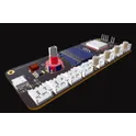
ESPRSSO32 Smart Scale AI Auto Layout [Example] xa24
Learn how to use AI Auto Layout on this ESP32 Espresso Smart Scale! In one click you’ll see AI Auto Layout perform magic. Pay close attention to how we recommend creating rulesets, zones, and fanouts. By copying the setup in this example on your own project, you’ll have a fully routed board in no time!
0 Uses1 StarsAerospace Electronics | Copilot Preset
Use this Copilot's template to design satellite payloads, avionic systems, or space instruments, considering MIL-STD, radiation hardening, and extreme environmental constraints. Modify project requirement properties to adapt to specific needs. #template #project-template
0 Uses1 StarsESPRSSO32 Smart Scale AI Auto Layout [Example]
Learn how to use AI Auto Layout on this ESP32 Espresso Smart Scale! In one click you’ll see AI Auto Layout perform magic. Pay close attention to how we recommend creating rulesets, zones, and fanouts. By copying the setup in this example on your own project, you’ll have a fully routed board in no time!
0 Uses1 StarsRealistic Brown Battle Mech
Nice — you can do a clean pulse + latch using a single quad Schmitt-NAND chip: 74HC132 (or 74LVC132 for 3.3 V systems). The HC132 contains four 2-input NAND gates with Schmitt inputs so you can both clean a noisy SYN480R DATA line and build an SR latch (NAND SR is active-LOW) inside one package. Only a few passives and a driver transistor are needed. Below is a ready-to-build recipe (parts, wiring, explanation, tuning tips, and an ASCII schematic) — no extra logic ICs required. Parts (per latch) 1 × 74HC132 (quad 2-input NAND with Schmitt inputs). If your system is 3.3 V use 74LVC132 / 74HC132 rated for 3.3 V. Rin = 47 kΩ (input series) Cfilter = 10 nF (input RC to ground) — tweak for debounce/clean time Rpulldown = 100 kΩ (pull-down at input node, optional) Rpullup = 100 kΩ (pull-up for active-LOW R input so reset is idle HIGH) Rbase = 10 kΩ, Q = 2N2222 (NPN) or small N-MOSFET (2N7002) to drive your load Diode for relay flyback (1N4001) if you drive a coil Optional small cap 0.1 µF decoupling at VCC of IC Concept / how it works (short) Use Gate1 (G1) of 74HC132 as a Schmitt inverter by tying its two inputs together and feeding a small RC filter from SYN480R.DATA. This removes HF noise and provides a clean logic transition. Because it's a NAND with tied inputs its function becomes an inverter with Schmitt behavior. Use G2 & G3 as the cross-coupled NAND pair forming an SR latch (active-LOW inputs S̄ and R̄). A low on S̄ sets Q = HIGH. A low on R̄ resets Q = LOW. Wire the cleaned/inverted output of G1 to S̄. A valid received pulse (DATA high) produces a clean LOW on S̄ (because G1 inverts), setting the latch reliably even if the pulse is brief. R̄ is your reset input (pushbutton, HT12D VT, MCU line, etc.) — idle pulled HIGH. Q drives an NPN/MOSFET to switch your load (relay, LED, etc.). Recommended wiring (pin mapping, assume one chip; use datasheet pin numbers) I’ll refer to the 4 gates as G1, G2, G3, G4. Use G4 optionally for additional conditioning or to build a toggler later. SYN480R.DATA --- Rin (47k) ---+--- Node A ---||--- Cfilter (10nF) --- GND | Rpulldown (100k) --- GND (optional, keeps node low) Node A -> both inputs of G1 (tie inputs A and B of Gate1 together) G1 output -> S̄ (S_bar) (input1 of Gate2) Gate2 (G2): inputs = S̄ and Q̄ -> output = Q Gate3 (G3): inputs = R̄ and Q -> output = Q̄ R̄ --- Rpullup (100k) --- VCC (reset is idle HIGH; pull low to reset) (optional) R̄ can be wired to a reset pushbutton to GND or to an MCU pin Q -> Rbase (10k) -> base of 2N2222 (emitter GND; collector to one side of relay coil) Other side of relay coil -> +V (appropriate coil voltage) Diode across coil If you prefer MOSFET low side switching: Q -> gate resistor 100Ω -> gate of 2N7002 2N7002 source -> GND ; drain -> relay coil low side
0 Uses1 StarsESP32 Robot Controller | AI Design Review Tutorial [Example] fukm
Spot the mistake! Learn how to use AI to conduct a design review on an ESP32-based control board. This project is ideal for autonomous or radio-controller robots featuring inputs for sensors, encoders, and a Flysky RC receiver, plus an I2C display for configuration.
0 Uses1 Stars
![Brainstorm a new project with AI [Example]](https://img-cdn.flux.ai/eyJidWNrZXQiOiJncmF2aXRvbi1lbGVjdHJpYy1zeW1ib2xzIiwia2V5IjoiZG9jdW1lbnRfYXNzZXRzL0JyYWluc3Rvcm0tdy1Db3BpbG90LTFkNGM1ODk0LTY2ZWMtNGFmYi05ZTAyLTU3YjRhMDk2MTdmNC5wbmciLCJlZGl0cyI6eyJyZXNpemUiOnsid2lkdGgiOjEyNCwiaGVpZ2h0IjoxMjQsImZpdCI6ImNvbnRhaW4iLCJiYWNrZ3JvdW5kIjp7InIiOjAsImciOjAsImIiOjAsImFscGhhIjowfX19LCJvdXRwdXRGb3JtYXQiOiJ3ZWJwIn0=)



![ESPRSSO32 Smart Scale AI Auto Layout [Example] xa24](https://img-cdn.flux.ai/eyJidWNrZXQiOiJncmF2aXRvbi1lbGVjdHJpYy1zeW1ib2xzIiwia2V5IjoiZG9jdW1lbnRfYXNzZXRzL0VTUFJFU1NPMzJfU21hcnRfU2NhbGVfM0RfVGh1bW5haWwtY2QxNTI2NjItNjdjMi00MTk4LWJmNjUtNDJiZDk5N2E0ODYyLnBuZyIsImVkaXRzIjp7InJlc2l6ZSI6eyJ3aWR0aCI6MTI0LCJoZWlnaHQiOjEyNCwiZml0IjoiY29udGFpbiIsImJhY2tncm91bmQiOnsiciI6MCwiZyI6MCwiYiI6MCwiYWxwaGEiOjB9fX0sIm91dHB1dEZvcm1hdCI6IndlYnAifQ==)

![ESP32 Robot Controller | AI Design Review Tutorial [Example] fukm](https://img-cdn.flux.ai/eyJidWNrZXQiOiJncmF2aXRvbi1lbGVjdHJpYy1zeW1ib2xzIiwia2V5IjoiZG9jdW1lbnRfYXNzZXRzL1RodW1ibmFpbC1FU1AzMi0tMS0tZTNjNjM0OGEtYjEzMy00YjliLWEyYTItMzY1MGNiMjgyYWJiLnBuZyIsImVkaXRzIjp7InJlc2l6ZSI6eyJ3aWR0aCI6MTI0LCJoZWlnaHQiOjEyNCwiZml0IjoiY29udGFpbiIsImJhY2tncm91bmQiOnsiciI6MCwiZyI6MCwiYiI6MCwiYWxwaGEiOjB9fX0sIm91dHB1dEZvcm1hdCI6IndlYnAifQ==)