Top Organization Projects
Explore the top organization projects on Flux.ai, featuring noteworthy printed circuit board (PCB) designs from variousindustries. This collection includes PCB projects developed by businesses and institutions, highlighting practical and innovative approaches to design. The top organization projects offer insight into the standards and practices of professional PCB design. It's a useful resource for designers and organizations aiming to understand industry trends and solutions. By showcasing projects from diverse organizations, Flux.ai provides a platform for sharing knowledge and techniques within the electronics design community.
Fast Silver Flubber
Create a schematic diagram of an electric fence controller using the NE556 dual timer IC. The circuit must include all components with clear electronic symbols (resistors, capacitors, transistors, diode, relay) connected by lines as in a real circuit diagram. Specifications: 1. Power supply: - Vcc = +12V connected to pin 14 of the NE556. - Pin 1 of the NE556 to ground. 2. Timer A (active 10 seconds): - Pin 2 (Trigger A) receives a pulse from transistor Q2 (contact detector). - Pin 6 (Threshold A) connected to Pin 7 (Discharge A). - R1 = 1 MΩ between Pin 7 and +12V. - C1 = 10 µF between Pin 6 and ground. - Pin 3 (Out A) goes through a 4.7 kΩ resistor to the base of Q1 (BC547 NPN transistor). - Pin 3 also connected via a 100 nF capacitor to Pin 13 (Trigger B of Timer B). 3. Timer B (rest 10 seconds): - Pin 9 (Discharge B) and Pin 8 (Threshold B) connected together. - R2 = 1 MΩ between Pin 9 and +12V. - C2 = 10 µF between Pin 8 and ground. - Pin 12 (Out B) can be optionally used to block retrigger of Timer A. 4. Relay driver stage: - Q1 = BC547 NPN transistor. - Base connected through 4.7 kΩ resistor to Pin 3 (Out A). - Emitter to ground. - Collector connected to one side of the relay coil. - Other side of relay coil connected to +12V. - A diode 1N4007 placed in parallel with the relay coil (cathode to +12V, anode to collector of Q1). - Relay contacts switch the +12V supply to the electric fence energizer. 5. Contact detector: - Shunt resistor ≈0.1 Ω placed in series with the fence output. - Q2 = BC547 NPN transistor, base connected to the shunt, emitter to ground, collector to Pin 2 (Trigger A). - When current flows through the shunt, Q2 provides a trigger pulse to Timer A. Please draw the schematic in a standard style with components connected by straight lines, not in block diagrams. Show clear pin numbers of the NE556 and all external components.
0 Uses1 StarsWily Orange TARDIS
Objetivo: leer coordenadas X/Y en un panel resistivo casero con Arduino Nano. Componentes: Arduino Nano, 16 MHz, 5 V (1x) MCP23017, expansor I/O I²C de 16 pines (1x) ADS1115, ADC I²C 16 bits (1x) Panel táctil casero, 2 láminas aluminio (1x) Resistencias serie 4.7 kΩ – 10 kΩ (4x) Fuente 5 V (USB/external) Funcionamiento: MCP23017 controla X+/X-/Y+/Y- → aplica 5 V y GND al eje activo. Ejemplo: para leer X → MCP energiza X+/X-, deja Y flotante. ADS1115 mide voltaje en el eje sin energía (ej: Y+/Y-) en modo diferencial. Arduino Nano recibe lecturas por I²C, procesa coordenadas X/Y. Coordenadas enviadas por USB serial al PC. Conexiones: Arduino Nano ↔ I²C bus ↔ MCP23017 y ADS1115 (SDA, SCL en común). MCP23017 pines → X+/X-/Y+/Y- (con resistencias serie). ADS1115 entradas analógicas → eje libre (Y+/Y- o X+/X- según ciclo). Alimentación común: 5 V + GND.
0 Uses1 StarsMarried Red Electromagnetic Shrinking Machine
The Smart Hospital Bed is designed to enhance the care and comfort of patients with limited mobility by streamlining repositioning and maintaining detailed health records. It features automated repositioning options via an intuitive control interface, along with a rotating mechanism that allows the bed to transform into a chair for better comfort and adaptability. Additionally, its health data recording system provides real-time data base record on vital signs and posture, accessible remotely by healthcare providers helps them with decision making.
0 Uses1 StarsArduino Uno R3 Shield Template hvke
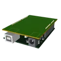
Template for Arduino Uno R3 Shield. Include an official pinout so you will always know Arduino names, the alternative roles of pins, which one is SDA, or SCL, etc. On PCB you can find the 3D model of the Arduino Uno R3 itself along with the board outline on the silkscreen. #Arduino #Uno #Shield #Template #project-template #project
0 Uses1 StarsESPRSSO32 Smart Scale AI Auto Layout [Example] W/ Polygons [Staging V1_9-9-25]
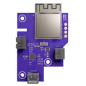
Learn how to use AI Auto Layout on this ESP32 Espresso Smart Scale! In one click you’ll see AI Auto Layout perform magic. Pay close attention to how we recommend creating rulesets, zones, and fanouts. By copying the setup in this example on your own project, you’ll have a fully routed board in no time!
0 Uses1 Stars

![ESPRSSO32 Smart Scale AI Auto Layout [Example] W/ Polygons [Staging V1_9-9-25]](https://img-cdn.flux.ai/eyJidWNrZXQiOiJncmF2aXRvbi1lbGVjdHJpYy1zeW1ib2xzIiwia2V5IjoiZG9jdW1lbnRfYXNzZXRzL0VTUFJFU1NPMzJfU21hcnRfU2NhbGVfM0RfVGh1bW5haWwtY2QxNTI2NjItNjdjMi00MTk4LWJmNjUtNDJiZDk5N2E0ODYyLnBuZyIsImVkaXRzIjp7InJlc2l6ZSI6eyJ3aWR0aCI6MTI0LCJoZWlnaHQiOjEyNCwiZml0IjoiY29udGFpbiIsImJhY2tncm91bmQiOnsiciI6MCwiZyI6MCwiYiI6MCwiYWxwaGEiOjB9fX0sIm91dHB1dEZvcm1hdCI6IndlYnAifQ==)